EasyManua.ls Logo

Toshiba TVL Series - Page 128

Toshiba TVL Series
154 pages
To Next Page IconTo Next Page
To Previous Page IconTo Previous Page
Loading...
TRANSPORTATION AND INSTALLATION MANUAL
128
Input/output signal connector HAND (TSL3100 Type-P)
Pin
Signal name
Signal No.
Input/output circuit and example of connections
1
D_IN1
Input signal 1
201
P24G
P24V
Contact or
transistor
Customer’s side
TS3100
[Sink type (-Common)]
2
D_IN2
Input signal 2
202
3
D_IN3
Input signal 3
203
4
D_IN4
Input signal 4
204
5
DC 24V (P24V)
6
D_OUT1
Output signal 1
201
Customer’s
side
DC relay
Diode for preventing counter
electromotive voltage
[Source type (+Common)]
P24V
P24G
7
D_OUT2
Output signal 2
202
8
D_OUT3
Output signal 3
203
9
D_OUT4
Output signal 4
204
10
DC 24V GND (P24G)
Input/output signal connector HOUT3, HOUT4 (Type-P)
(This connector is located in arm 2 (1), and connected to the solenoid valve when the
manifold is optional.)
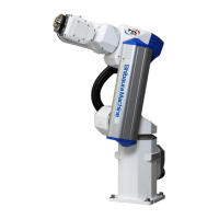
Pin (Connector): HOUT3)
Signal name
Signal No.
1
D_OUT5
Output signal 5
205
2
D_OUT6
Output signal 6
206
3
DC 24V GND (P24G)
Pin (Connector): HOUT4)
Signal name
Signal No.
1
D_OUT7
Output signal 7
207
2
D_OUT8
Output signal 8
208
3
DC 24V GND (P24G)
Input
Arm 2 (1)
Output

Table of Contents

Related product manuals