- 6 - tousek / E_PULL-T5-T8-T10_49002305 / 19. 12. 2013
NOTE concerning cable laying
• The electric cables have to be laid in insulating sleeves which are suitable for underground usage. The insulat-
ing sleeves have to be lead into the inner of the operator housing (see picture).
• 230V cables and control lines have to be laid in separate sleeves.
• Only double-insulated cables, which are suitable for underground usage (e.g. E-YY-J) may be used.
• In case that special regulations require another type of cable, cables according to these regulations have to be
used.
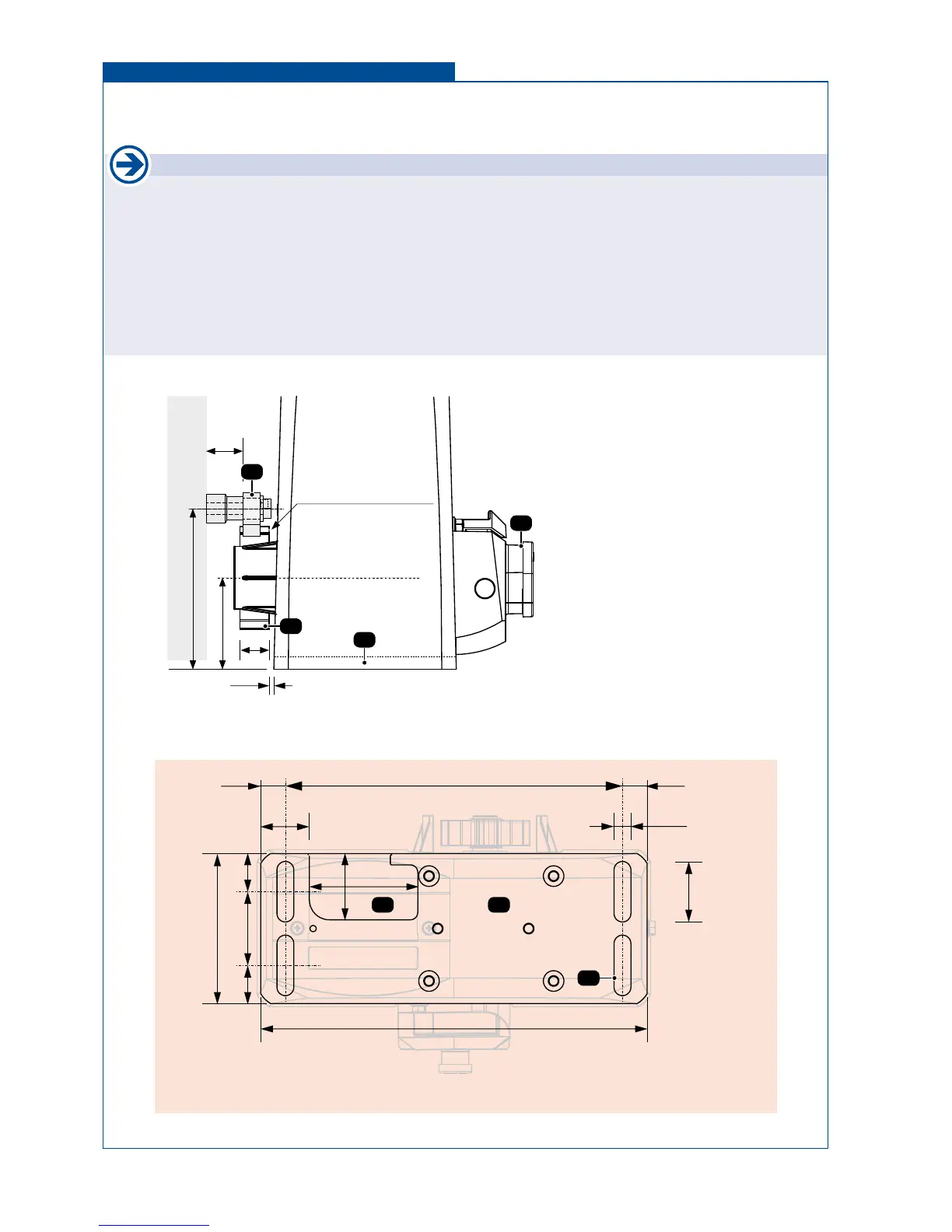
2.1 Installation of the motor Installation
(1) lockable emergency release (PHZ)
(2) gear wheel
(3) cable
(4) ground plate
(4a) slotted holes (4x) for connection on
the ground
(Z) steel gear rack
After installing the protection tubes (check cable exit of operator (3)) and having nished the concrete foundation, the
motor has to be bolted through the 4 slotted holes (4a) to the concrete foundation. It is particularly important that the
operator is mounted parallel to the gate panel, and that the measurements given in the drawing are kept.
63
22
121 (PULL T5,-T8)
113 (PULL T10)
25
2
Z
4
1
3,4
gear wheel:
PULL T5,-T8: Z20M4, r44
PULL T10: Z16M4, r36
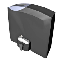
Foundation
43
4a
272
48,5
58,5
40
85
52
13,5
119,5
309
30,530,5
18,5 18,5