- 14 - tousek / E_PULL-T5-T8-T10_49002305 / 19. 12. 2013
Important
• Jumper J of transmitter and receiver has
to be adjusted in the same way.
Photocells
• The control unit has a power supply connection for a 24V a.c. photocell (LS):
supply LS-transmitter: terminals 40/41 / supply LS-receiver: terminals 40/43.
Note: in „gate closed“ position the terminals 40/41 are being switched into energy saving mode - no current
(only if no radio transmission system TX 310 is used) !
• The contact has to be closed when using powered and positioned photocells (opening contact).
Connection of the photocell contact: terminals 45/46
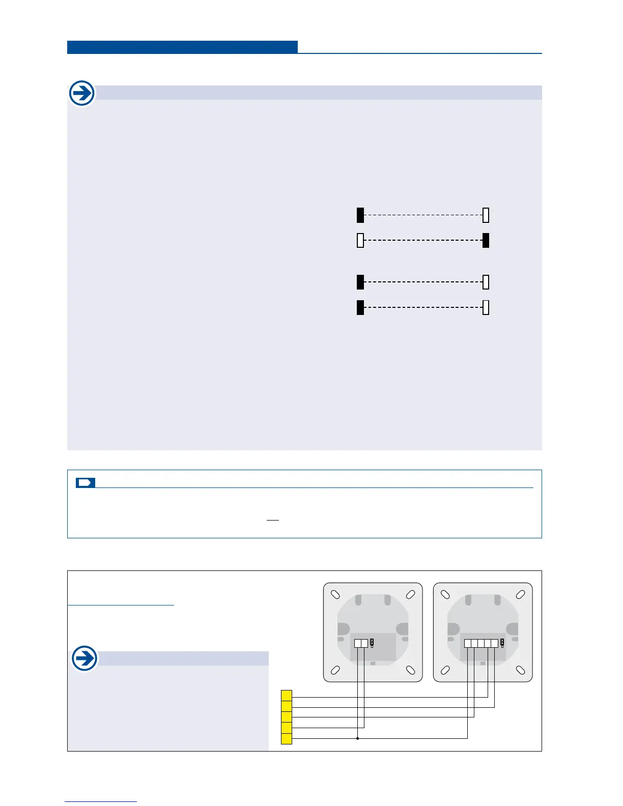
• When using two pairs of photocells please do not
install both photocell transmitters/receivers on the
same side (to eleminate interference between both) !
Exception: photocells with SYNC function allow the
installation of both photocell transmitters/receivers on
the same side without causing interference to each
other.
• Photocell self-test function:
The control board is equipped with a self-test function for the connected photocell. With an opening impulse (switch or
button) the transmitter of the photocell is switched off for a short time in gate position „closed“ . Thus the photocell receiver
interrupts the contact 45/46 - so the control board veries the function of the photocell receiver. If this short interruption
at the photocell input is not carried out, the control board reports an error. The deactivation of the self-test function
is only allowed if the safety installations correspond to the category 3 !
• The exact function of the photocells depend on the programming of the control unit.
Photocell function please see menu point SAFETY / photocell function or photocell with pause time (S. 17)
• Youwillnddetailed information in the corresponding photocell manual.
Standard:
transmitter 1 receiver 1
receiver 2 Sender2
With SYNC-function:
transmitter 1 receiver 1
transmitter 2 receiver 2
G
Photocell (Contact: terminals 45/46) Safety
active: to be selected, if photocell should be triggered.
not active: to be selected, if photocell should not be triggered.
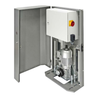
Photocell - connection examples
Photocell Tousek LS 26
as safety device
46
45
43
41
40
+
~
-
~
12/24V
J
+
~
-
~
12/24V
NC C NO
J
transmitter receiver
Safety Connections and adjustments