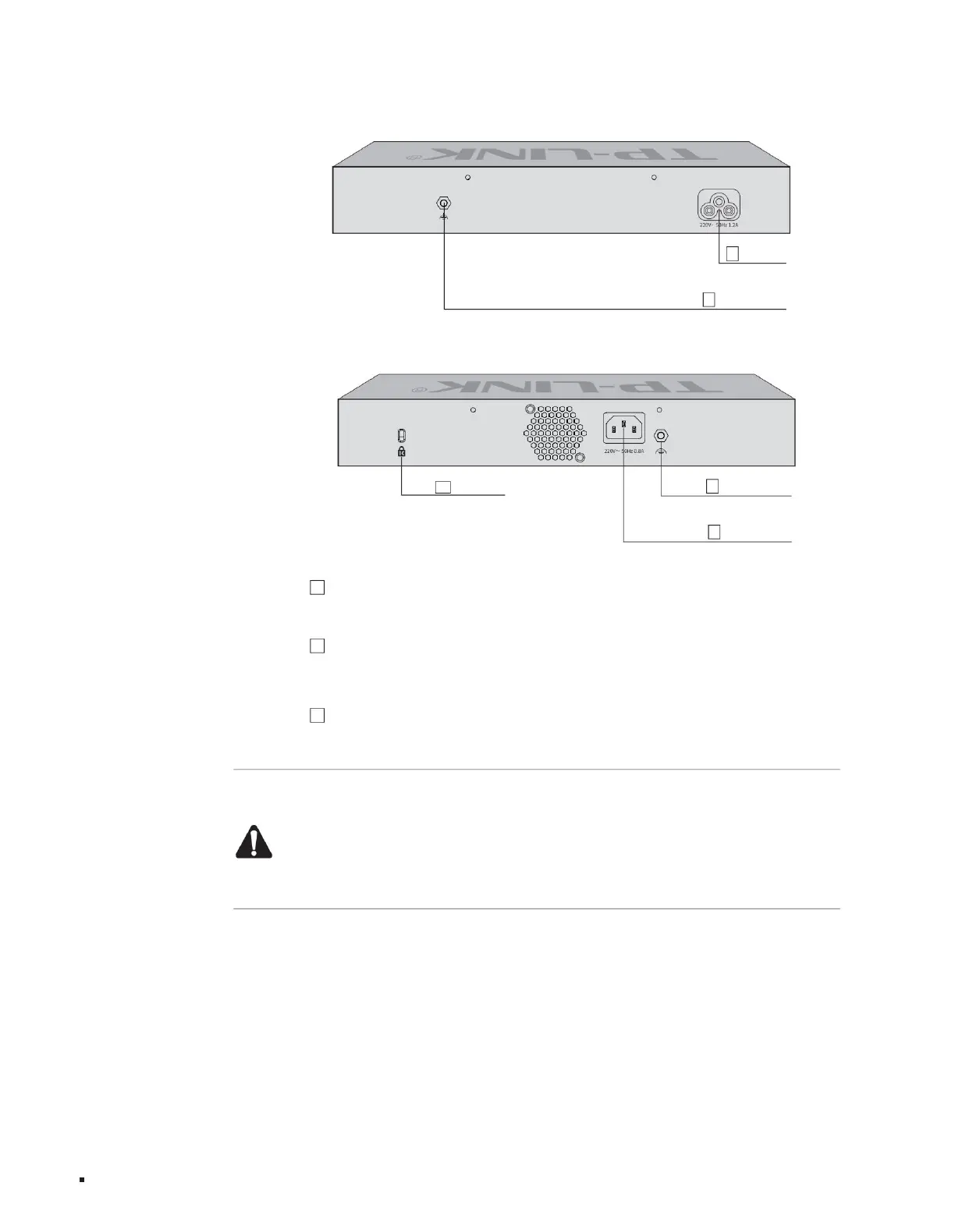
The rear panel of TL-ST5008 is shown in the figure below.
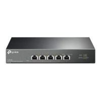
The rear panel of TL-ST5012 is shown in the figure below.
Lightning protection grounding post 1
3 anti-theft lock holes
1Lightning protection grounding post
2
power sockets
2
product description
Power outlet
Layer 3 managed switch installation manual
3 Kensington anti-theft lock hole To prevent
the switch from being stolen, the Kensington anti-theft lock can be fixed into the security lock hole.
Figure 1-8 Rear panel diagram
Note:
ÿPlease use the original power cord.
ÿPlease connect the product to an output socket with a ground connection through the power cord plug. ÿThe
plug on the power cord serves as a disconnecting device and the socket should be easily
accessible. ÿPlease keep away from water, fire, humid or hot
environments. ÿPlease do not attempt to disassemble, repair or
modify the device. ÿDo not replace the battery, otherwise there is a risk of explosion.
1Lightning protection terminal
Please use yellow and green double-colored copper core wires for grounding to prevent lightning strikes. For details, please refer to the "Lightning Protection Installation Manual".
07
Figure 1-7 Rear panel diagram
2 Power socket This
is a power socket with a protective grounding. Connect the negative plug of the power cord to this socket, and the positive plug to the AC power
supply, and connect to the 220V~50Hz AC power supply.
Machine Translated by Google