ÿ Rear panel
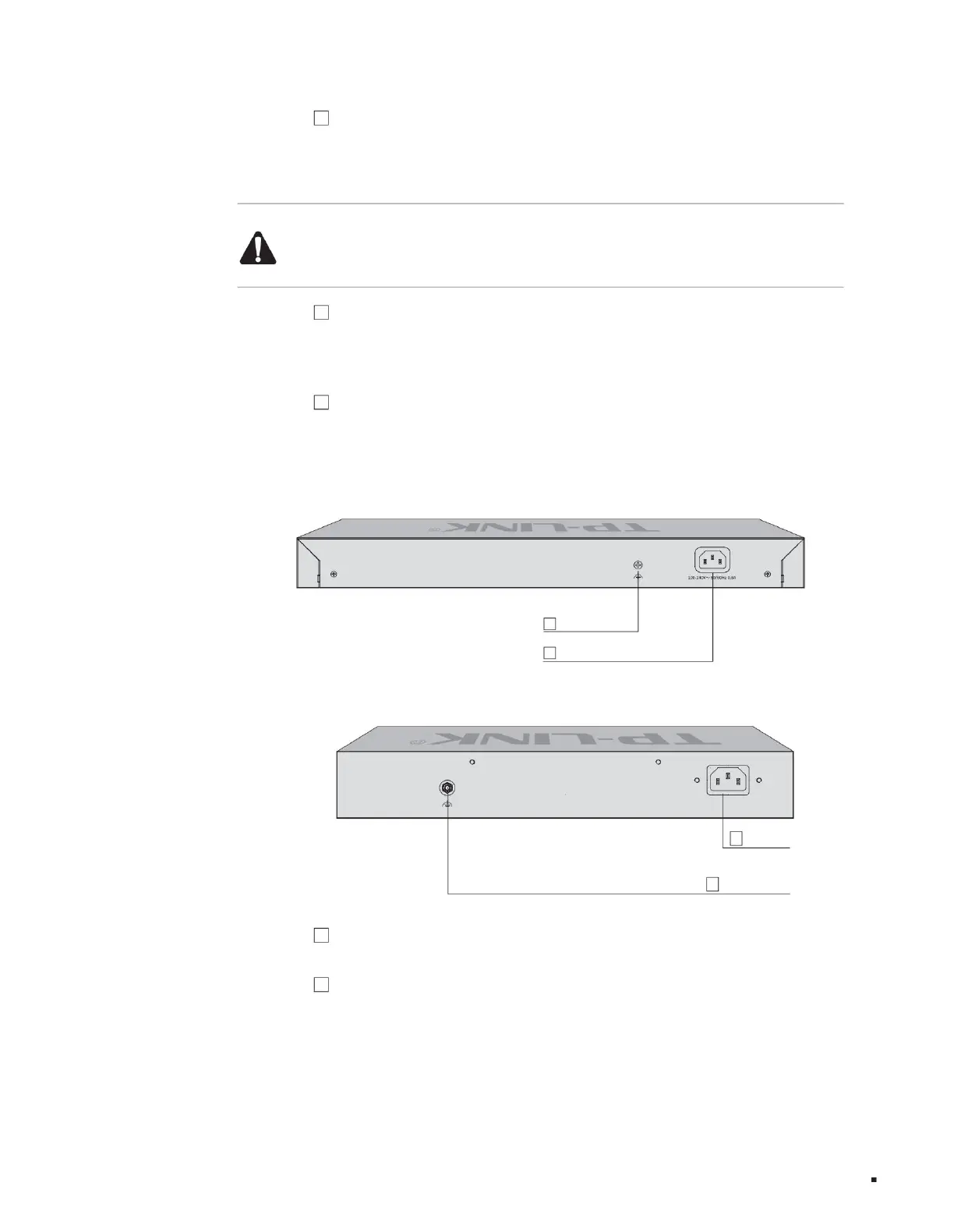
The rear panel of the TL-ST5012F switch is shown in the figure below.
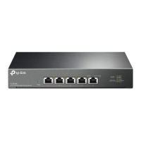
The rear panel of the TL-ST5016F switch is shown in the figure below.
1
2
2
Lightning protection grounding post 1
product description
Lightning protection grounding post
Power outlet
Power outlet
Layer 3 managed switch installation manual
3 USB ports are
standard USB2.0 ports, supporting an upload and download rate of 480Mbps. Through this port, users can interact with the Flash file system
on the switch, such as uploading or downloading application files, configuration files, etc. Supports switch U disk deployment. For detailed
function introduction, please refer to the "User Manual".
Note:
Due to differences in compatibility and drivers of USB devices from different manufacturers, TP-LINK does not guarantee that USB devices from all
manufacturers can be used normally on the TL-ST5008. If a USB device cannot be used normally, it is not a switch failure. In this case, please try to use
a USB device from another manufacturer.
Figure 1-5 Rear panel diagram
4 8 10Gbps adaptive RJ45 ports support 10Gbps rate
adaptation function and automatic flip (Auto-MDI/MDIX) function. Each port corresponds to three Link/Act indicators. The left side of the port is
the 10Gbps indicator, and the two lights on the right correspond to the 5G/2.5Gbps indicator (green) and the 100M/1Gbps indicator (yellow).
Figure 1-6 Rear panel diagram
1. For lightning protection
terminals, please use copper core wires with yellow and green sheaths for grounding to prevent lightning strikes. For details, please refer to the "Lightning Protection Installation Manual".
06
5 1 Type-C Console port The Console port is
used to connect to the serial port of a computer or other terminal to manage the switch.
2 Power socket This
is an AC power socket. Connect the female plug of the power cord to this socket and the male plug to the AC power supply. The switch is
connected to an AC power supply of 100-240V~ 50/60Hz.
Machine Translated by Google