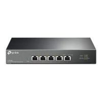
The front panel of TL-ST5012 is shown in the figure below.
2
5 12 10Gbps adaptive RJ45 ports
product description
3 1 USB port 4 1 Type-
C Console port
1 indicator light
Flashing system is normal
System exception
Yellow always on
Flashing system power supply abnormality
Steady green or off
Turn off this device and it is not the stack master device.
PWR power indicator light
Master stack indicator
SYS system indicator light
An error occurred in electing the stack master device, or other types of stack errors
occurred.
Always on, the system power supply is normal.
Off, the system is not powered on or the power supply is abnormal.
Steady green
This device is the stack master device, or the stacking function has been enabled but has not been
stacked independently.
Indicator name working status working description
Mode switch
Layer 3 managed switch installation manual
5 Management port
03
3 Console port The
Console port is used to connect to the serial port of a computer or other terminal to manage or configure the switch.
TL-ST5016F provides 1 Type-C Console port and 1 RJ45 Console port. The two ports cannot be used at the same time. When
connected at the same time, only the Type-C Console port takes effect.
The Management port is the switch management port, which can be used to connect a computer to enter the switch's Web management interface.
The factory default management IP is: 10.20.30.40. Users need to configure it through the Web management interface or CLI command line. For
specific configuration methods, see Chapter 4 Configuration Guide. . The management port is only used for management and does not participate
in data forwarding of the switch service port.
6 USB ports:
Standard USB2.0 ports, supporting upload and download rates of 480Mbps. Through this port, users can interact with the Flash
file system on the switch, such as uploading or downloading application files, configuration files, etc. TL-ST5016F supports switch
USB deployment. For detailed function introduction, please refer to the "User Manual".
Figure 1-3TL-ST5012 front panel diagram
4 10Gbps SFP+ ports
1 Indicator
lights, including PWR, SYS, Master, Stack, and USB indicators. You can monitor the working status of the switch through the
indicator lights, see the table below.
Note:
Due to differences in compatibility and drivers of USB devices from different manufacturers, TP-LINK does not guarantee that USB devices
from all manufacturers can be used normally on the TL-ST5016F. If a USB device cannot be used normally, it is not a switch failure. In this
case, please try to use a USB device from another manufacturer.
The SFP+ port supports access to 1000Mbps/2.5Gbps SFP optical/electrical modules or 10Gbps SFP+ optical/electrical modules.
Machine Translated by Google