22
HDWA-SVX001D-EN
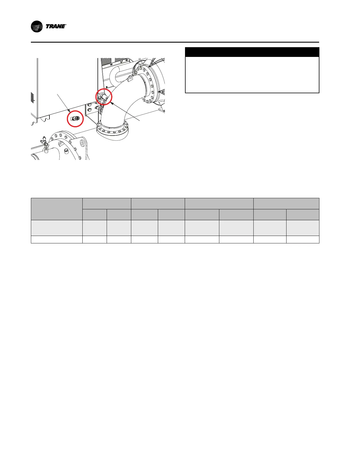
Figure 12. Location of relief valves
Condenser
Pressure
Relief Valve
Evaporator
Pressure
Relief Valve
Condenser
E
vaporator
Relief valve connection sizes and locations are shown
in unit submittals. Refer to local codes for relief valve
vent line sizing information.
NNOOTTIICCEE
EEqquuiippmmeenntt DDaammaaggee!!
FFaaiilluurree ttoo ccoommppllyy wwiitthh ssppeecciiffiiccaattiioonnss mmaayy rreessuulltt iinn
ccaappaacciittyy rreedduuccttiioonn,, uunniitt ddaammaaggee aanndd//oorr rreelliieeff vvaallvvee
ddaammaaggee..
DDoo NNOOTT eexxcceeeedd vveenntt ppiippiinngg ccooddee ssppeecciiffiiccaattiioonnss!!
Relief valve discharge setpoints and capacities rates
are provided in the following table. After the relief
valve has opened, it will re-close when pressure is
reduced to a safe level.
NNoottee:: After they are opened, relief valves may have
tendency to leak and must be replaced.
Pressure relief valve discharge capacities varies with
shell diameter and length and also compressor
displacement. Discharge venting capacity should be
calculated as required by ASHRAE Standard 15-94. Do
NOT adjust relief valve setting in the field.
Table 6. Pressure relief valve data
Valve Location
Discharge Setpoint Rated Capacity Field Connection Pipe Size
Factory Shell Side
Connection
psi
kPa
lb air/
min.
kg air/
min.
NPT
mm
in.
mm
Evaporator—
Compressor Low Side
Pipe (Suction)
200 1379.0 78.8 35.7
1-1/4
31.8
1-5/8 - 12
41.3 – 304.8
Condenser 300 2068.4 49.2 22.3
3/4
19.1
7/8 - 14
22.2 – 355.6
IInnssttaallllaattiioonn:: MMeecchhaanniiccaall