26
HDWA-SVX001D-EN
Strainers
NNOOTTIICCEE
WWaatteerr BBoorrnn DDeebbrriiss!!
TToo pprreevveenntt ccoommppoonneennttss ddaammaaggee,, ppiippee ssttrraaiinneerrss
mmuusstt bbee iinnssttaalllleedd iinn tthhee wwaatteerr ssuupppplliieess ttoo pprrootteecctt
ccoommppoonneennttss ffrroomm wwaatteerr bboorrnn ddeebbrriiss.. TTrraannee iiss nnoott
rreessppoonnssiibbllee ffoorr eeqquuiippmmeenntt--oonnllyy--ddaammaaggee ccaauusseedd
bbyy wwaatteerr bboorrnn ddeebbrriiss..
Install a strainer in the entering side of each piping
circuit to avoid possible tube plugging in the chiller
with debris.
Required Flow-Sensing Devices
The ifm efector® flow detection controller and sensor
(refer to “Water Flow Detection Controller and
Sensor,” p. 26) is used to verify evaporator and
condenser water flows.
If a customer-supplied flow sensing device is used to
ensure adequate chiller flow protection, refer to the
wiring diagrams that shipped with the unit for specific
electrical connections.
Be sure to follow the manufacturer’s recommendations
for device selection and installation.
Water Flow Detection Controller and
Sensor
IImmppoorrttaanntt:: Before installing the ifm efector
®
flow
detection controller and sensor, use a
marker to draw a line on the probe at 3.5 in.
(8.9 cm) from the end of the probe. Do NOT
insert more than 3.5 in. (8.9 cm) of the
probe length into the pipe. Refer to the
following figure.
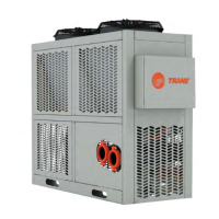
Figure 13. Installation of ifm efector flow detection
controller and sensor
Components:
A. E40174 – 1/2" NPT adapter (for ow probe)
B . SF6200 – Flow probe
C . SN0150 – Flow control monitor
D. E70231 – Combicon connectors (quantity 5)
E . E10965 – Micro DC cable, 10m length, PUR jacket
F. F53003 – Din rail, 40mm length
Output to
control cabinet
Jumper
N
L
AC
Jumper
Flow monitoring
Wire break monitoring
Temperature monitoring
Power-on delay time
Selection liquid / gas
Temperature monitoring can
also be incorporated using
terminals 10, 11, and 12.
To wire the ow monitoring
and wire-break monitoring
relay outputs in series, use
the wiring diagram at right.
Installation
1. Install adapter (A) into pipe.
2. Mount ow probe (B) into adapter (A).
3. Install DIN rail (F) into control cabinet.
4. Install control monitor (C) onto DIN rail (F).
5. Connect cable (E) to ow probe (B), (hand tighten only).
6. Wire cable in combicon connectors (D) according to
wiring diagram.
7. Wire relay outputs for ow, wire-break, and/or
temperature monitoring, according to wiring diagram.
If factory-provided,
located in control panel.
Do NOT insert more than
3.5 in. (8.9 cm) of the
probe length into the pipe.
4
3
2
1
Use a marker to draw a line
on the probe at 3.5 in. (8.9 cm)
from the probe end.
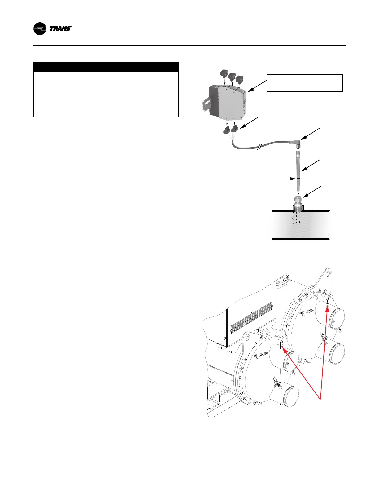
Figure 14. Location of ifm efector flow detection
controller and sensor
NNoottee:: In Agility
™
chillers, the ifm efector
®
flow
detection controller and sensor is mounted in the
waterbox nozzle, as shown in the preceding
figure.
IInnssttaallllaattiioonn:: WWaatteerr PPiippiinngg