HDWA-SVX001D-EN
45
Installing the Tracer AdaptiView
Display
During shipment, the Tracer® AdaptiView™ and
support arm are boxed, shrink-wrapped, and shipped
with unit. The display and support arm must be
installed at the site.
IImmppoorrttaanntt:: For best results, Trane, or an agent of
Trane, must install the Tracer
®
AdaptiView
™
display and support arm.
1. Unwrap the chiller. Locate the box containing the
Tracer® AdaptiView™ display and support arm
strapped to the shear plate between the condenser
and the evaporator (see the following figure).
2. Remove the display and support arm from the box.
NNoottee:: Display to support arm screws are M4 (metric
size 4), 6 to 8 mm long, and are shipped with
the display. Display arm screws are M6
(metric size 6), 16 mm long, washers, and
nuts used to secure arm to unit bracket are
shipped in the parts box.
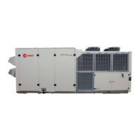
3. Using the M6 hardware shipped in the parts box,
attach the display support arm to the mounting
bracket on the side of the control panel (labeled A
and B in the following figure).
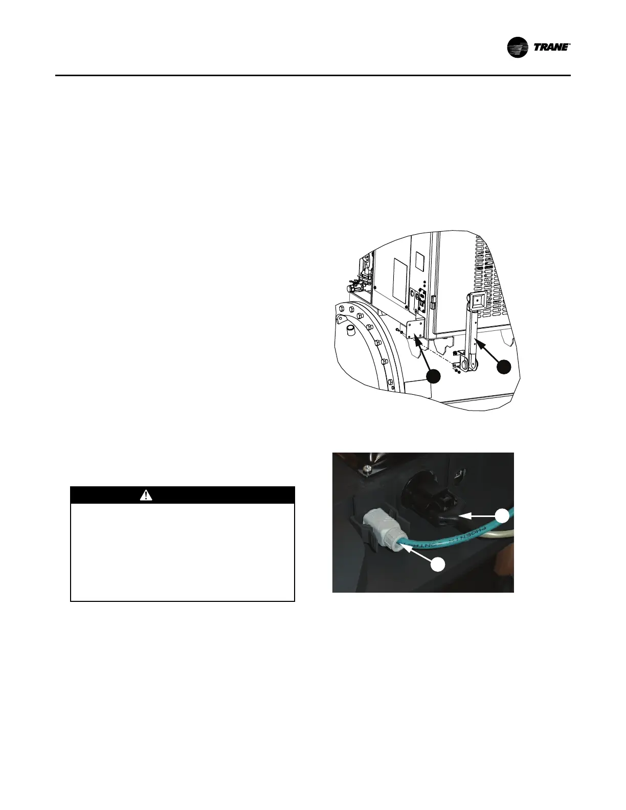
4. Plug the power cable (labeled C in the following
figure) and the Ethernet cable (labeled D in the
following figure) into the bottom of the display.
Plug other ends of the cables into the ports on the
side of the control panel.
5. Adjust the Tracer® AdaptiView™ display support
arm so the base plate that attaches to the display is
horizontal.
CCAAUUTTIIOONN
TTeennssiioonn iinn DDiissppllaayy SSuuppppoorrtt AArrmm!!
FFaaiilluurree ttoo ffoollllooww iinnssttrruuccttiioonnss bbeellooww ccoouulldd
rreessuulltt iinn uunneexxppeecctteedd mmoovveemmeenntt ooff tthhee sspprriinngg--
llooaaddeedd ssuuppppoorrtt aarrmm wwhhiicchh ccoouulldd rreessuulltt iinn mmiinnoorr
ttoo mmooddeerraattee iinnjjuurryy..
EEnnssuurree tthhaatt tthhee ssuuppppoorrtt aarrmm iiss iinn tthhee ffuullll
uupprriigghhtt ppoossiittiioonn wwhheenn rreemmoovviinngg tthhee TTrraacceerr
AAddaappttiiVViieeww ddiissppllaayy ffrroomm tthhee ssuuppppoorrtt aarrmm..
NNoottee:: Review “Adjusting the Tracer AdaptiView
Display Arm,” p. 46 before attaching the
display as some adjustments may be
required prior to attaching the display to the
support arm base.
6. Position the Tracer® AdaptiView™ display—with
the LCD screen facing up—on top of the display
support arm base plate.
NNoottee:: Ensure the Trane logo is positioned so that it
will be at the top when the display is attached
to the display support arm.
IImmppoorrttaanntt:: Use care when positioning the Tracer
®
AdaptiView
™
display on top of the
support arm base plate and do NOT
drop the display.
7. Align the four holes in the display with the screw
holes in the display support arm base plate.
8. Attach the Tracer® AdaptiView™ display to the
display support arm base plate (labeled E in the
following figure) using the M4 (metric size 4)
screws referenced in step 3.
Figure 28. Display arm installation
Figure 29. Power cable and Ethernet cable
connections
IInnssttaallllaattiioonn:: CCoonnttrroollss