28
HDWA-SVX001D-EN
NNOOTTIICCEE
PPrrooooff ooff FFllooww SSwwiittcchh!!
FFaaiilluurree ttoo pprroovviiddee ffllooww sswwiittcchheess oorr jjuummppiinngg--oouutt ooff
sswwiittcchheess ccoouulldd rreessuulltt iinn sseevveerree eeqquuiippmmeenntt
ddaammaaggee..
EEvvaappoorraattoorr aanndd ccoonnddeennsseerr wwaatteerr cciirrccuuiittss rreeqquuiirree
pprrooooff ooff ffllooww sswwiittcchheess..
•• FFaaiilluurree ttoo iinncclluuddee tthhee pprrooooff ooff ffllooww ddeevviicceess aanndd//
oorr jjuummppiinngg oouutt tthheessee ddeevviicceess ccoouulldd ccaauussee tthhee uunniitt
ttoo ssttoopp oonn aa sseeccoonnddaarryy lleevveell ooff pprrootteeccttiioonn..
•• FFrreeqquueenntt ccyycclliinngg oonn tthheessee hhiigghheerr lleevveell
ddiiaaggnnoossttiicc ddeevviicceess ccoouulldd ccaauussee eexxcceessssiivvee tthheerrmmaall
aanndd pprreessssuurree ccyycclliinngg ooff uunniitt ccoommppoonneennttss ((OO--rriinnggss,,
ggaasskkeettss,, sseennssoorrss,, mmoottoorrss,, ccoonnttrroollss,, eettcc..)) aanndd//oorr
ffrreeeezzee ddaammaaggee,, rreessuullttiinngg iinn pprreemmaattuurree ffaaiilluurree ooff
tthhee cchhiilllleerr..
Evaporator and condenser proof of flow switches are
required. These switches are used with control logic to
confirm flow prior to starting a unit and to stop a
running unit if flow is lost. For troubleshooting, a
viewable diagnostic is generated if a proof of flow
switch does not close when flow is required.
Evaporator and Condenser
Water Piping
The following two figures illustrate the recommended
(typical) water piping arrangements for the evaporator
and condenser.
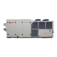
Figure 16. Typical evaporator water piping circuit
4
45
53
3
7
2
2 1
9
6
2
2
8
Outlet
Inlet
1. Balancing valve.
2. Gate (Isolation) valve or ball valve.
3. Thermometer (if field supplied).
4. Waterbox nozzle connection.
5. Drain, vent, and anode.
6. Strainer.
7. Chilled water flow switch (5S1). Flow switch 5S1
may be installed in either the entering or leaving leg
of the chilled water circuit.
8. Pump.
9. Pressure gauge. It is recommended to pipe the
gauge between entering and leaving pipes. A
shutoff valve on each side of the gauge allows the
operator to read either entering or leaving water
pressure.
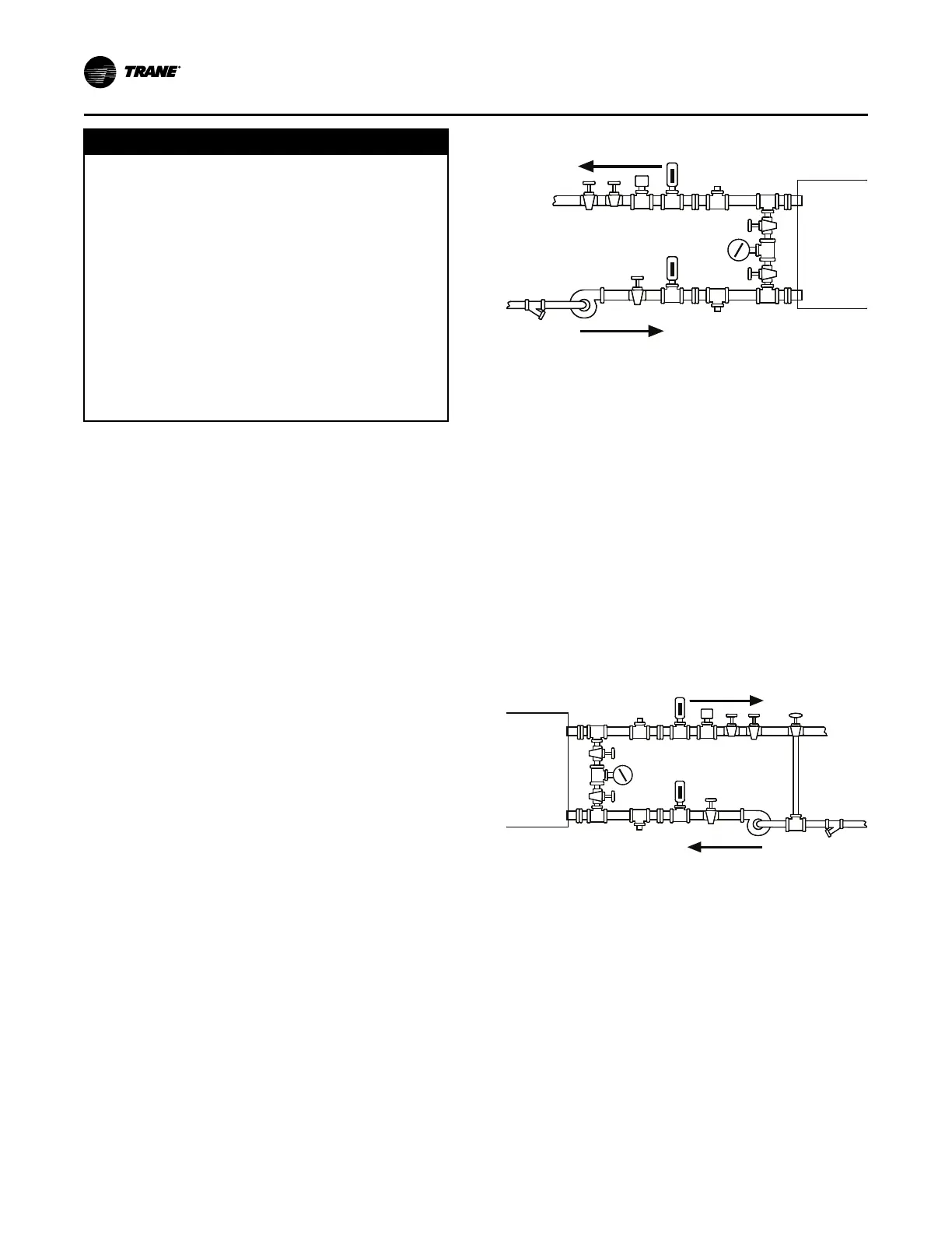
Figure 17. Typical condenser water piping circuits
1 2
3
4 5
6
7 8
92
3
4 5
2
2
10
Outlet
Inlet
1. Balancing valve.
2. Gate (isolation) valve or ball valve.
3. Thermometer (if field supplied).
4. Waterbox nozzle connection.
5. Drain, vent, and anode.
6. Strainer.
7. Condenser water flow switch (5S2). Flow switch
5S2 may be installed in either the entering or
leaving leg of the chilled water circuit.
8. Three-way valve (optional).
9. Condenser water pump.
10. Pressure gauge. It is recommended to pipe a single
gauge between entering and leaving pipes.
IInnssttaallllaattiioonn:: WWaatteerr PPiippiinngg