HDWA-SVX001D-EN
31
The flange-adapter gasket must be placed with the
color-coded lip on the pipe and the other lip facing the
mating flange.
NNOOTTIICCEE
PPiippiinngg CCoonnnneeccttiioonn LLeeaakkss!!
FFaaiilluurree ttoo pprroovviiddee eeffffeeccttiivvee sseeaall ccoouulldd rreessuulltt iinn
eeqquuiippmmeenntt oorr pprrooppeerrttyy--oonnllyy ddaammaaggee..
TToo pprroovviiddee eeffffeeccttiivvee sseeaall,, ggaasskkeett ccoonnttaacctt ssuurrffaacceess
ooff aaddaapptteerr mmuusstt bbee ffrreeee ooff ggoouuggeess,, uunndduullaattiioonnss oorr
ddeeffoorrmmiittiieess..
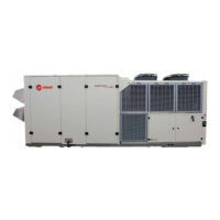
Victaulic Gasket Installation
1. Inspect supplied gasket to be certain it is suited for
intended service (code identifies gasket grade).
Apply a thin coat of silicone lubricant to gasket tips
and outside of gasket.
2. Install gasket, placing gasket over pipe end and
making sure gasket lip does not overhang pipe end.
Refer to the following figure for gasket
configuration.
3. Align and bring two pipe ends together and slide
gasket into position centered between the grooves
on each pipe. No portion of the gasket should
extend into the groove on either pipe.
4. Open fully and place hinged Victaulic® flange
around the grooved pipe end with the circular key
section locating into the groove.
5. Insert a standard hex head screw through the
mating holes of the Victaulic® flange to secure the
flange firmly in the groove.
6. Tighten fasteners alternately and equally until
housing screw pads are firmly together (metal-to-
metal); refer to “Screw-Tightening Sequence for
Water Piping Connections,” p. 31. Do NOT
excessively tighten fasteners.
NNoottee:: Uneven tightening may cause the gasket to
pinch.
Figure 20. Typical Victaulic®® flange gasket
configuration
Table 10. Installation data for 150 psig (1034.2 kPaG) flange adapters (Style 741)
Nominal Pipe Size
Assembly
Screw Size
(a)
Number of Assembly
Screws Required
Screw Pattern Diameter
Weight
in.
mm
in. in.
mm
lb
kg
6 168.3
3/4 x 3-1/2
8 9.5 241 10.3 4.7
8 219.1
3/4 x 3-1/2
8 11.75 298 16.6 7.5
(a)
Screw size for conventional flange-to-flange connection. Longer screws are required when flange washer must be used. Grade 5 screws are
recommended.
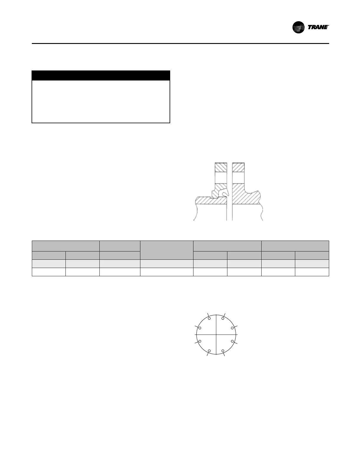
Screw-Tightening Sequence for
Water Piping Connections
This section describes a screw-tightening sequence for
flanges with flat gaskets or O-rings. Remember that
improperly tightened flanges may leak.
NNoottee:: Before tightening any of the screws, align the
flanges.
Flanges with 8 Screws
Tighten all screws to a snug tightness, following the
numerical sequence for the appropriate pattern as
shown in the following figure. Repeat this sequence to
apply the final torque to each screw.
Figure 21. Flange screw tightening sequence (8
screws)
IInnssttaallllaattiioonn:: WWaatteerr PPiippiinngg