14
Description of the components
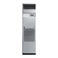
A - User terminal
Allows the unit to be turned on or off and the con guration
and visualization of the condition of the machine.
• A1 LCD Display
• A2 ALARM key:visualization and reset of alarms; when
the alarm is activated, it ashes red
• A3 PRG key: access to the con guration menu
• A4 ESC key : exit from the screens
• A5 UP key : scroll through the menu
• A6 ENTER key : con rm
• A7 DOWN key: scroll through the menu
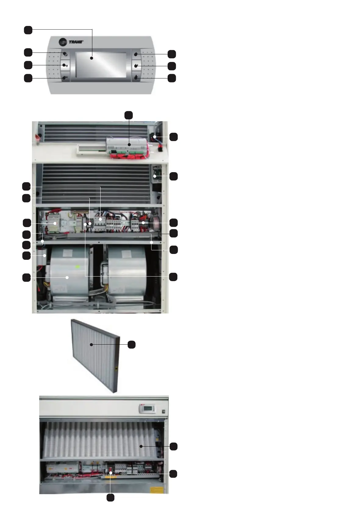
B - Electrical panel door
Allows access to the electrical panel of the machine.
C - Cover panel
D5
D1
D2
D3
D6
D
7a
I
D?
D
7b
D
7c
D
7d
Allow access to the internal components of the machine.
D - Electrical panel
• D1 Magnetothermic
- auxiliary
- heater (optional)
- humidi er (optional)
- fans
- compressors
• D2 Interface board
• D3 Dirty lter sensor
• D4 Air ow sensor
• D5 Main switch
• D6 Terminal board
• D7a Input/output electrical supply cables
• D7b Input/output electrical auxiliary cables
• D7c Input/output condensing unit supply (optional) - Only
on units with air cooling
• D7d Entrance/exit signal cables (RS485 and/or LAN)
• D8 Phase sequence relay
E - Air Filter
E
Filter the air released into the environment
F - Fans
F1
F
D8
E
D
D5
 Loading...


