RT-SVD03G-EN 11
Module Flow Diagram
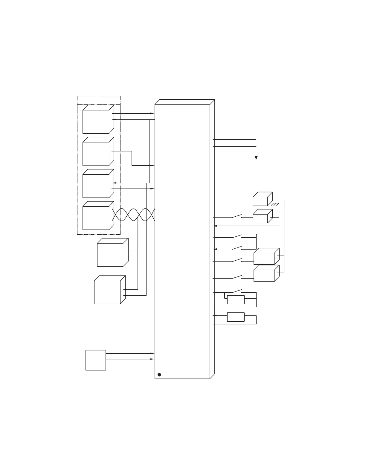
Figure 1. TSC/THC Refrigeration Module (RTRM) Electric Heat/No Heat
LED or indications
TS/H Refrigeration Module
4 Zone Sensor Inputs (AIP)
4 Outputs
Non Heat Pump Config (BIP)
1 Compressor Config (BIP)
1 Stage Heat Config (BIP)
4 Thermostat inputs (BIP)
3 to 7 wire Communicating ZSM
Indoor Fan Output (BOP)
MODBUS Communication
Compressor 1 Output (BOP)
Compressor 1 Proving (BIP)
Compressor 1 Disable (BIP)
Emergency Stop (BIP)
Electric Heat 1st Stage
Electric Heat 2nd Stage
Service Test input (BIP)
Outdoor Air Temp (AIP)
LEDs: System TX, RX
24 VAC
Power
Sensor
Resistor
Electric
Heat 2
Electric
Heat 1
CC1
IDF
Unit Control, Select one
Zone Sensor
Mechanical
Thermostat
G Y1 Y2 W1
R C/B
Zone Sensor
Programmable
COMM 3/4
Communication
Interface
Options
Module
Economizer
Module
w/Actuator