RT-SVD03G-EN 25
ReliaTel Refrigeration Module (RTRM)
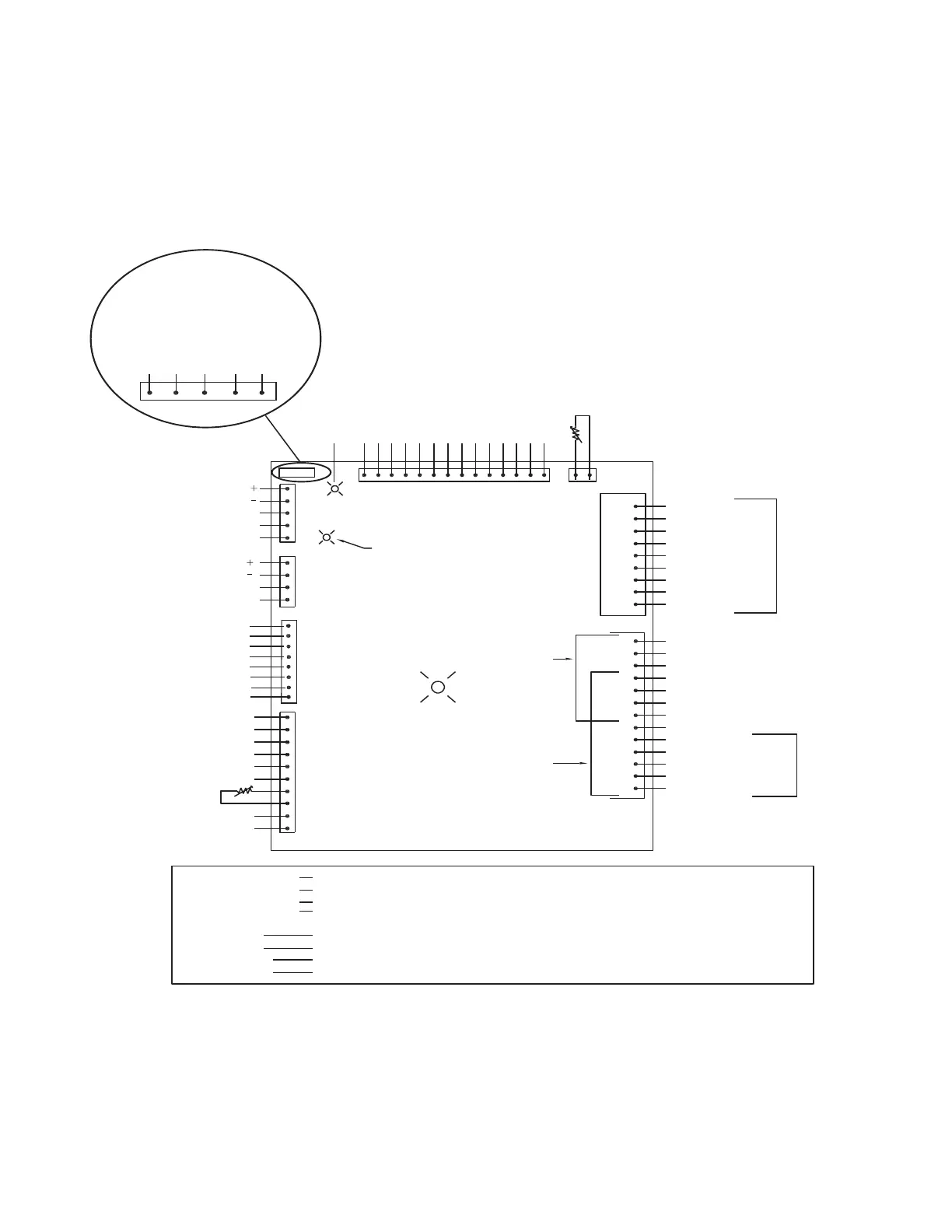
Figure 16. ReliaTel Refrigeration Module (RTRM) - Layout
Transmit LED
(Green)
Common
24 VAC
2 Stage Heat Config
24 VAC
Lead/Lag Config
CC2 Output
CC2 Proving
LPC 2 Input
24 VAC In
24 VAC In
Heat 1
Heat 2
SOV 1
ODF B Relay Output
Coil Temperature
Sensor
Electric Config
Common
Heat Pump/
Electric
Heat
J2
Green LED
“System”
2 Compressor
Units
J3
J5
J4
ModBus
Communication
Gas Heat
Communication
Receive LED
(Yellow)
Conventional
Thermostat
Programmable
Zone
Sensor
Module
J7
J6
Mechanical
Conventional
Thermostat
Common
T
X2
Y2
W2
G
W1 (YC, TC) O (WC)
Y1
R (24 VAC)
C
T
X2
Y2
W2
G
W1/O
Y1
R
14
12
11
10
6
7
8
4
5
9
1
2
3
24 VAC
Communication Input for Prog. ZSM
Common
ClogFilter/Fan Failure Indication
System/Test Indication
Cool/Cool Fail Indication
Heat/Heat Fail Indication
Common
Heating Setpoint
Mode Input
Cooling Setpoint
Common
Zone Temp Input
Mechanical
ZSM
Green System LED
Green TX LED
Yellow RX LED
On - Normal
Off - No Power, Board Failure
Blinking - Test Mode
Two 1/4 Second Blinks Every 2 Seconds
Diagnostic Present (Version 4.0+)
Off - No Power, Board Failure
1/4 Second Blink Every 2 Seconds - No ModBus Communication
Very Fast Flash .5 Second, Off 1.5 Second - ModBus Communication Occuring
24 VAC
Common
Config Common
Config - 1 Compressor
Config - Non Heat Pump
Config - 1 Stage Heat
LPC 1 Input
CC 1 Proving
Fan Relay Output
Emergency Stop
Test 2
Test 1
Outdoor
Air Sensor
1
2
1
2
3
4
5
6
7
8
9
10
11
13
12
14
J1
J8
1
3
2
5
4
1
2
3
4
1
2
3
4
5
6
7
8
1
2
3
4
5
6
7
8
9
10
Two 1/4 Second Blinks Every 2 Seconds - Diagnostic Present
*
*
To enable lead/lag on multiple compressor units, cut wire connected to J-3-8
J9
J9
1 2 3 4 5
OUTDOOR COIL TEMP
2 COMMON/CONFIG
COMMON
OUTDOOR COIL TEMP
2 Signal
INDEPENDENT CIRCUIT/
MOD DEHUMID CONFIG
FAN PROVING Input
RTRM FAN FAIL CONFIG
Config - Extended Heat
Config - EDC Disable
3-Step Cooling Input
ODF A Relay Output
Windmill Prevention Disable
SOV 2
Compressor 1 Relay Output