RT-SVD03G-EN 151
Voyager Commercial 27½ to 50 Tons CV and VAV
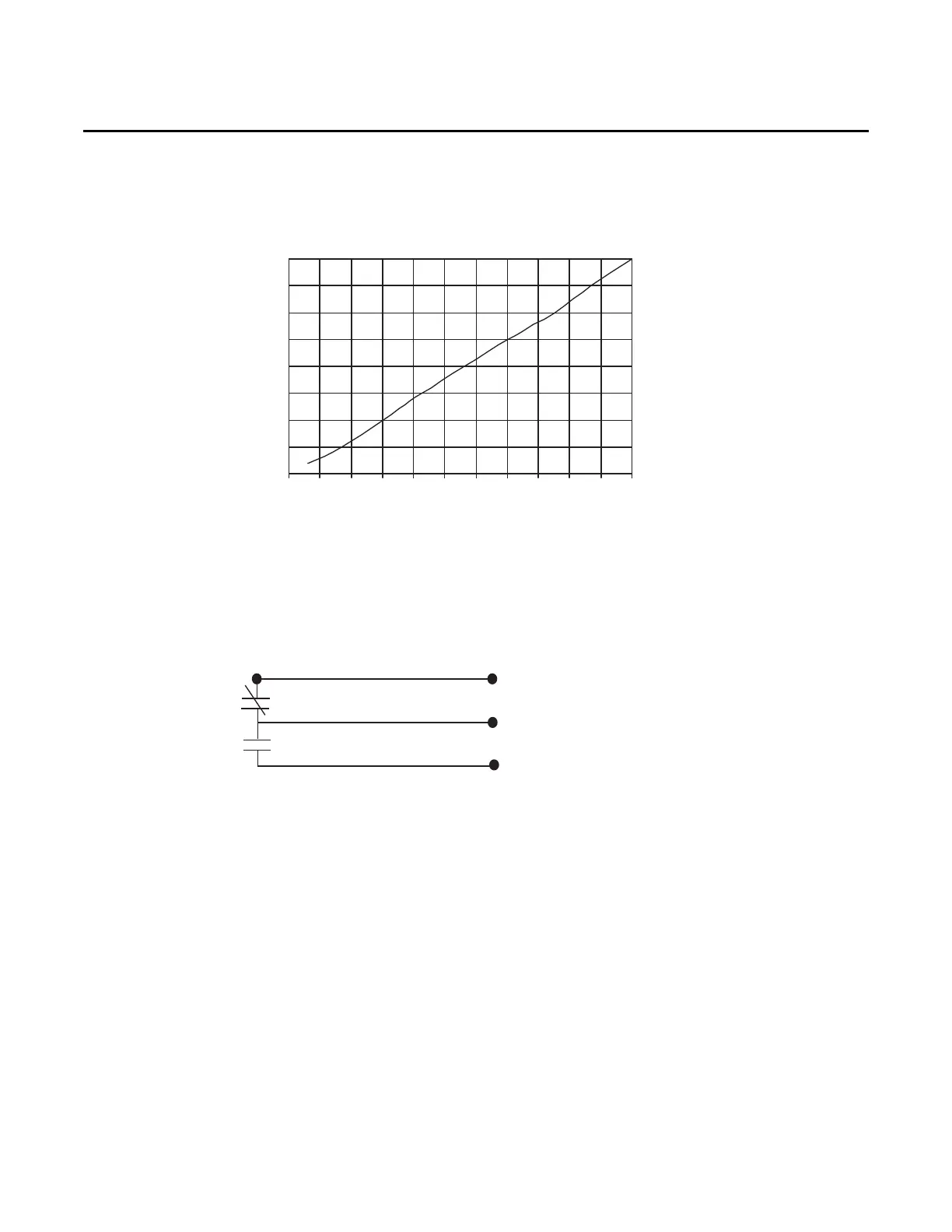
The transducer has a 0 to 5VDC range with a 0.25 to 2.125 VDC valid output range. The output is
proportional. The chart illustrates the measured output voltage at typical supply duct pressures.
VHR Relay
When the unit transitions from occupied mode to morning warmup, daytime warmup or
unoccupied mode, the VHR relay is energized, as long as the unit has a valid zone temperature input
at RTRM J6 1&2, or through a BAYSENS020* zone sensor.
The VHR relay has a set of contacts on TB3 for the purpose of commanding the VAV boxes to drive
open to maximum airflow position.
If the unit has heat, the VAV boxes must be driven open. If the boxes are allowed to stay in control,
the boxes may try to close instead of open when the warm air enters the room.
Additional notes:
1. When RTAM DIP SW1-1 is on, the output voltage range is approximately 0 to 10.5VDC.
2. When RTAM DIP SW1-1 is off, the output voltage range is approximately 2.5 to 8.5VDC.
3. IGV: When the supply fan is on and the output is 0%, the IGV are closed.
4. VFD: When the supply fan is on and the output is 0%, the VFD runs at 35hz.
5. If the supply static pressure goes below -0.2" (0.2VDC) the IGV / VFD output will stay at 0% and
the diagnostic COOL FAIL + SERVICE FAIL will be present.
6. If the static pressure exceeds 3.8" WC the supply fan will stop and the diagnostic HEAT FAIL +
COOL FAIL +SERVICE FAIL will be present.
7. During the heating modes; Daytime Warm-up, Morning Warm-up, and Unoccupied, the IGV or
VFD output is always 100%.
Figure 85. Transducer Voltage Output vs. Pressure
Transducer Voltage Output vs Pressure Input
0.0
0.5
1.0
1.5
2.0
2.5
3.0
3.5
4.0
-0.5 0.0 0.5 1.0 1.5 2.0 2.5 3.0 3.5 4.0 4.5 5.0
Pressure (inches w.c.)
Volts