RT-SVD03G-EN 149
Voyager Commercial 27½ to 50 Tons CV and VAV
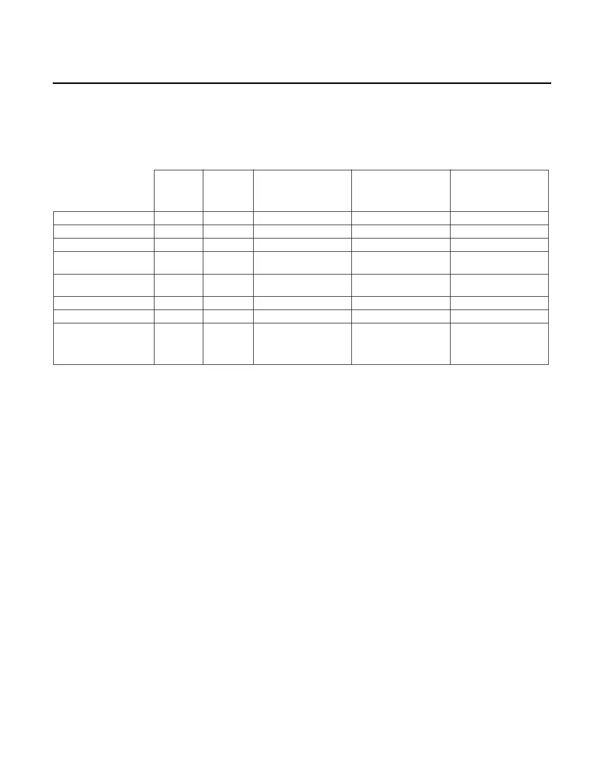
Unit functions are determined by the inputs on RTRM J6 as follows. The possible inputs are shown
in the top (horizontal) row. The functions available are shown in the vertical columns below each
input.
Supply Duct Static Pressure Control
The supply duct static pressure is measured by using a 0 to 5VDC transducer. The transducer is
mounted on the supply fan bulkhead on the motor side of the supply fan section. The transducer
is comparing the supply duct pressure (actually the pressure of the heat section of the unit) to
outdoor air pressure. The high port of the transducer is connected to the static pressure sensing
cover plate located on the supply fan bulkhead. The low port of the transducer is connected to a
tubing connector on a vertical support of the unit and is field-connected to the Outside Air Pressure
Sensor as pictured below. The transducer is wired to the RTAM and the decision to modulate the
IGV or VFD is made at the RTRM.
Modes of Operation
Setpoints are provided by using the potentiometers on the RTAM, through remote potentiometers,
or through ICS. The setpoint range is 0.3" WC to 2.5" WC. The deadband range is 0.2" WC to 1.0" WC.
The control band is the setpoint plus or minus ½ of the deadband.
For example:
Setpoint 1.5"
Deadband 0.4"
The IGV or VFD output will increase if the supply pressure goes below 1.3".
The IGV or VFD output will decrease if the supply pressure goes above 1.7"
The IGV or VFD output will not change if the supply pressure stays between 1.3" and 1.7".
DIP switch settings for this function are as follows:
RTAM SW1 switch 1 OFF for IGV, ON for VFD.
RTAM SW1 switch 2 OFF for VAV, ON for "VAV without IGV".
Table 48. VAV Default Mode Input
No Inputs
on RTRM
J6
Jumper
RTRM J6-
2&4
BAYSENS077A w/
RTRM J6-2&4 Jumper
BAYSENS021* or
BAYSENS077A w/
7.68k resistor
between RTRM J6-2&4
BAYSENS020* or ICS™
system (Tracer
Summit)
Occupied Cooling
No Yes Yes Yes Yes
Daytime Warm-up
No No Yes Yes Yes
Morning Warm-up
No No Yes Yes Yes
Indoor Blower
(occupied mode)
OffOnOnOnOn
Indoor Blower
(unoccupied mode)
N/A Off Auto Auto Auto
Unoccupied Cooling
N/A No No No Yes
Unoccupied Heating
N/A No Yes Yes Yes
Short Across RTRM J6-
11&12 creates an
unoccupied mode
(Night setback)
No No Yes Yes N/A
Note: * Means 'B' or 'C'