63
Additional Thermostat / Zone Sensor Info
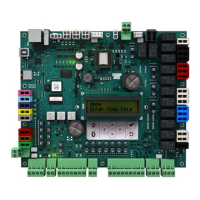
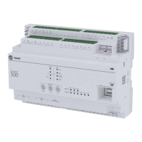
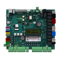
On the Symbio 700 UC J19-7 and J21-1 are current limited to 1.1 amps.
On the Symbio Relay Board J5-2 is current limited to 300 ma.
Open voltage on sensors is 2.5 volts, divide Reliatel Values in half.
Open sensor and a shorted sensor reports 200°
If someone uses the BAYSENS109 or 110 they can’t hook up J19-6 & 7 to the Symbio because that is
now 24VAC and Common, J19-8, 9 and 10 are not present.
With a thermostat
On Symbio heat pumps, Y1 + W2...after a 3-minute delay for compressor(s) to come on the electric heat
comes on within 30 seconds
Symbio 700 (UC) Y1 + X2 nothing will run, not even the indoor fan.
Symbio 700 (UC) Y1 + W2 + X2 nothing will run, not even the indoor fan.
Y2 before Y1 – Circuit 1 on, Add Y1 after 3 minutes – Circuit 2 on, remove Y2 – Circuit 2 off, remove Y1 –
Circuit 1 off.
Y1 and Y2 together – Both compressors on together (5 seconds apart) the assumption is that the
thermostat manages inter-stage delays.
Symbio (UC) Heat Pump a W2 by itself will turn on heat.
Symbio Relay Board Y1 + Y2 + W1 + W2 will still activate the heat outputs.
 Loading...
