Installation
12 CDUB-SVN001B-EN
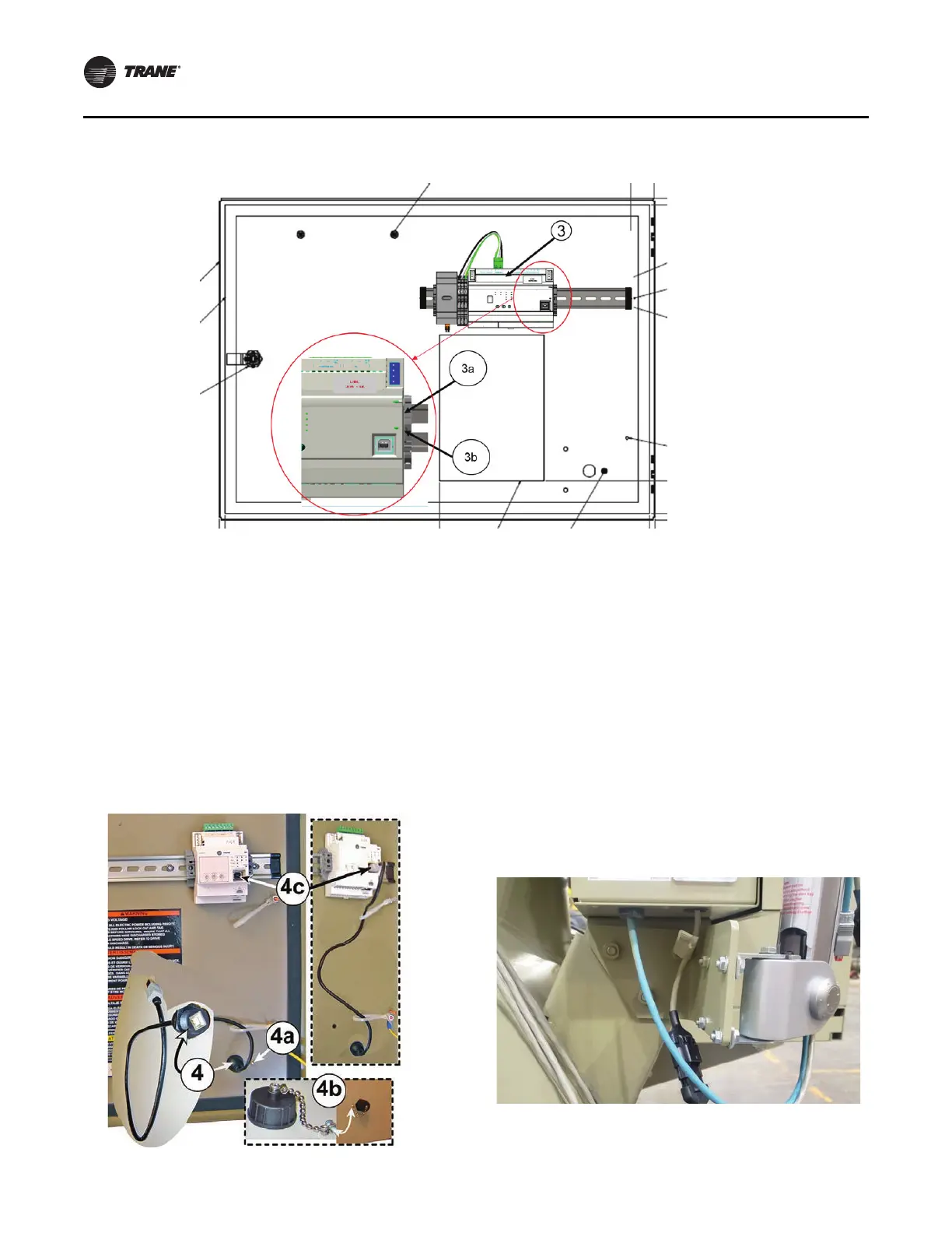
4. Install the round end of the USB Type B service port
cable into the cut-out on the door and secure it with the
plastic nut.
a. Remove the rubber protective p
l
ug from the inside
of the weld nut.
b. Secure the dust cover to the
outside of the door by
inserting the #4-40 x 0.25-inch machine screw
provided through the shackle on the end of the cap
chain, and then threading the screw into the weld
nut.
c. Plug the opposite end of the USB cable into the
ap
propriate port in the Symbio 800 controller.
Choosing Display Arm Mounting
Location
Recommended mounting location:
The display arm assembly is designed to be secured to the
side
of the control panel or to one of the two mounting
brackets underneath the control panel enclosure.
Note: We
al
so provide a production display arm bracket
BRK04345 provided that where applicable can be
mounted to the existing right hand side control
panel mounting arm. When used, the holes on the
unused side should be plugged. It is preferable to
secure the arm to the right-hand mounting bracket,
which is at the opposite end of the control panel
enclosure from the door hinges.
Figure 13. Mounting Symbio 800 controller onto new control panel door
Figure 14. Installation of the USB service port cable
Figure 15. Production arm bracket
 Loading...


