Installation
CDUB-SVN001B-EN 25
Mount transducers on the entering and leaving side water
box locations with the transducer facing upwards and
connect to unit control buss. After system is filled, loosen
the transducer in its threaded fitting. Then crack the
isolation valve until water starts dripping from threads.
Close the valve and re-tighten the transducer, and then re-
open the valve for use.
High Accuracy Customer Meter Option
The high accuracy customer meter option provides an
analog input/output LLID to monitor a customer provided
high accuracy meter 0-10 Vdc or 4 – 20 mA outputs.
(Rosemont, etc.) This option allows monitoring of
condenser, evaporator flow and auxiliary heat
exchangers.
Install needed DAIO LLID(
s) (BRD04875) in CVRF control
panel:
1. LLID (1A21) is needed for EVAP and COND water flow.
Conne
ct flow meter wires to 1A21-J2-1 and 1A21-J2-1
for EVAP, 1A21-J2-4 and 1A21-J2-5 for COND.
2. LLID (1A28) is need for HR Aux/COND water
flow.
Conne
ct flow meter wires 1A28-J2-1 and 1A28-J2-1 for
HR flow or Aux COND.
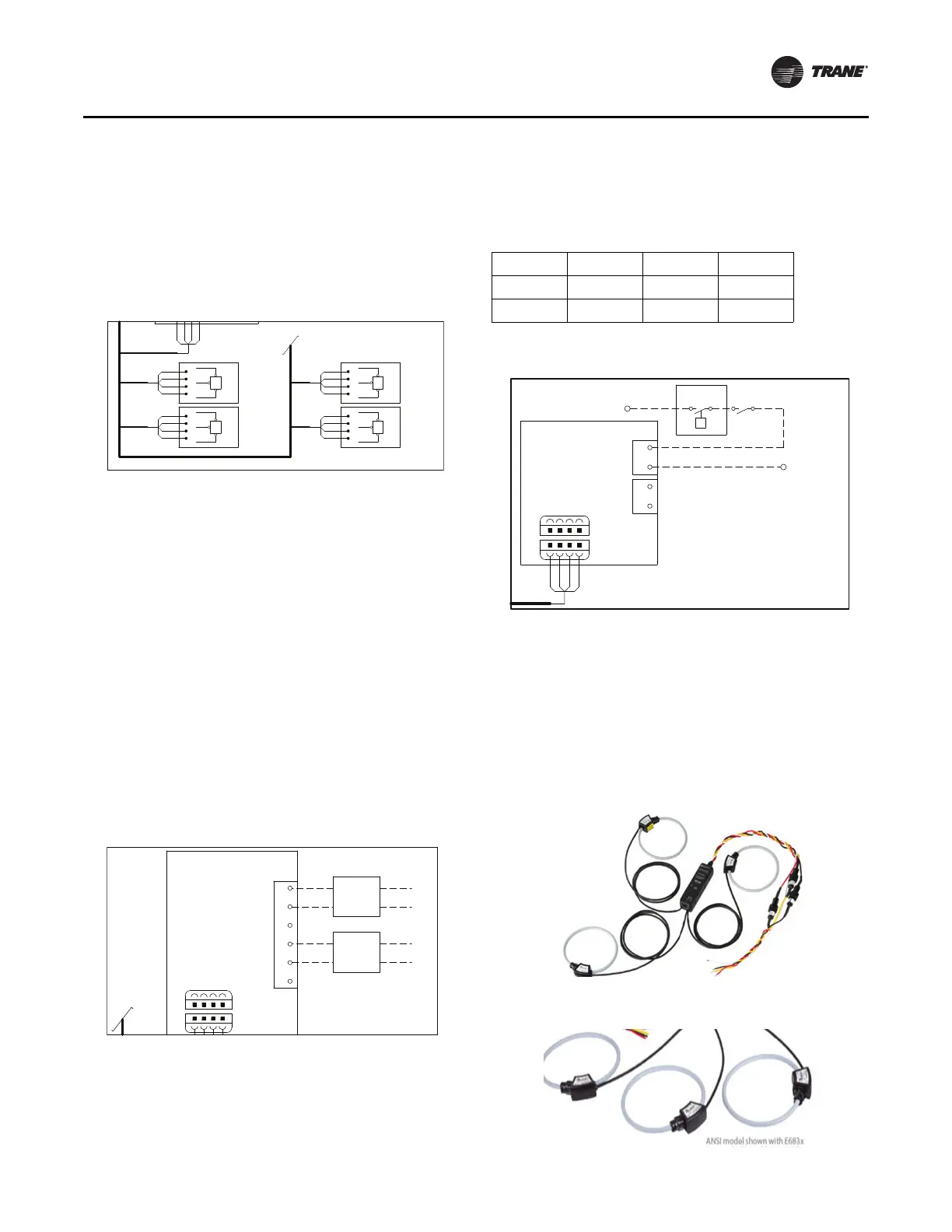
Heat Recovery/Aux COND Option
When heat recovery/Aux COND option is selected, a
DHVBI LLID (BRD04874) is required as 1A29 and wires
matrix show as following:
Energy Meter Option Installation
The Trane energy meter provides instrument grade
accuracy power, volts and amps monitoring of Symbio
controls installations. It has 1% accuracy for measuring
both real power and energy and reactive power and
energy. All data measured by the meter is communicated
via Modbus to Symbio control system. For more detail
information, refer to BAS-SVN224*-EN.
Figure 47. Standard accuracy flow meter wiring,
ref.
50712792
Figure 48. High accuracy customer meter flow meter
wiring, ref. 50712792
WATER PRESSURE
EVAP ENTERING
OPTIONAL
TRANSDUCER
WATER PRESSURE
EVAP LEAVING
OPTIONAL
TRANSDUCER
WATER PRESSURE
COND ENTERING
OPTIONAL
TRANSDUCER
WATER PRESSURE
COND LEAVING
OPTIONAL
TRANSDUCER
IPC BUS
FLOW METER
RED
-
Pg
+
SIG
4BP4
-
Pg
+
SIG
4BP5
-
Pg
+
SIG
4BP6
-
Pg
+
SIG
4BP7
1A21 DUAL ANALOG I/O
OPTIONAL
INPUT 1
OUTPUT 1
2
1
GND
INPUT 2
OUTPUT 2
GND
4
3
J2
5
6
COND FLOW METER
5B2 CUSTOMER PROVIDE
4-20mA
FLOW
METER
OUTPUT
EVAP FLOW METER
5B1 CUSTOMER PROVIDE
SIGNAL
24VDC
1A2 J3-1
0V
4-20mA
FLOW
METER
24VDC
1A1 J3-1
0V
1A2 J3-2
1A1 J3-2
OUTPUT
SIGNAL
IPC BUS
4
4
J11
1
J1
1
OPTIONAL WATER FLOW METER
CUSTOMER PROVIDE 4-20MA INPUT
Table 3. Wire matrix
Wire # AWG From To
14B 16 1A29-J3-2 1X1-21
2K 16 1A29-J3-1 1X2-10
Figure 49. Heat recovery/Aux COND flow switch wiring
Figure 50. Energy meter
Figure 51. Rogowski CTs
1X1-15
d
P
5S11 5K3
REQUIRED OPTIONAL
AUX CONDENSER
WATER FLOW SWITCH
HEAT RECOVERY
1X1-7
1A29 DUAL HIGH VOLTAGE BINARY INPUT
4
4
1
2
1
J2
RED
J11
J1
1
1
J3
2
WATER FLOW SWITCH
AUX CONDENSER
HEAT RECOVERY
OPTIONAL
 Loading...


