Installation
26 CDUB-SVN001B-EN
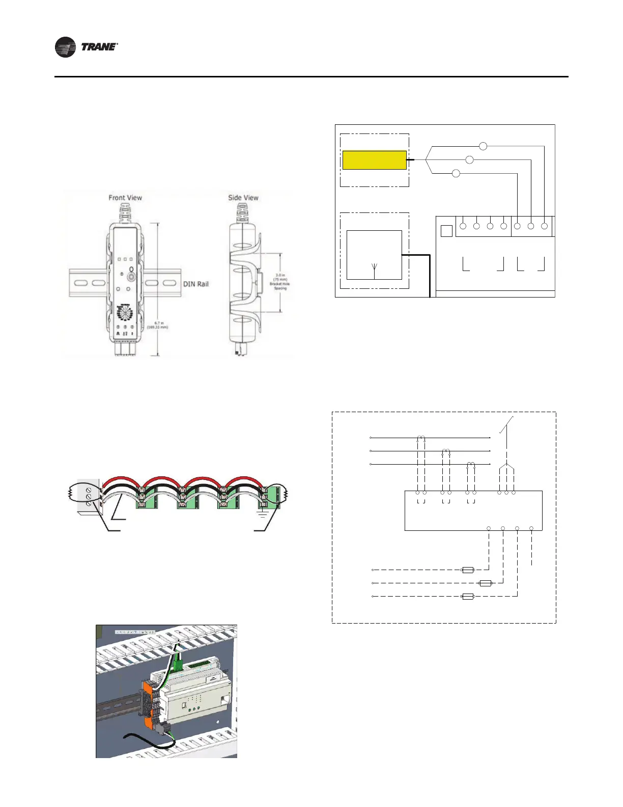
The meter is connected to line voltage of up to 480 volts
and should be mounted within the starter cabinet. It is
provided with a mounting bracket that can either be
mounted on DIN rail or directly to cabinet wall. It is
mountable using the provided bracket.
The meter is connected to Modbus communications and is
self-powered by
the unit voltage potential inputs. Review
meter literature for setup and operation details.
Modbus communications is by shielded 14 – 26 AWG
cabl
e fro
m meter to Symbio module. Install 120 OHM
resistors at first and last modules on Modbus daisy chain.
The communications wiring will be terminated at the
Mo
dbus distribution terminal (1X3) beside Symbio 800
using the 3 poles connector which provide in energy meter
kits.
480 Volts and Lower Installations
POTENTIAL INPUT – Install provided fused inputs to line
voltage per schematic.
CURRENT INPUT – Install provided Rogowski CTs per
schematic.
Expansion Module Option
CDUB retrofit panel reserve place of expansion module
beside Symio 800 controller. There are few configurations
that depend on I/O requirements and din rail length.
Currently din rail in CDUB panel is 13.9 inch, could add one
XM32 or two XM30 at most. If XM70 is selected, a 20-inch
din rail is required, in 0185-3495-0100. For detailed I/O
information, refer to 50712794.
Figure 52. Mount energy mete
r with strap tunnel on
rail
Figure 53. Sheilded cable
Figure 54. Modbus distribution terminal
–
S
+
Shielded Wire
120 terminators on the first/last devices of daisy
chain
Ω
Figure 55. Communication wiring, ref. 50712792
Figure 56. 480V Energy meter wiring, ref. 50712756
-
+
BACKNET
P1
-
+
-
+
MODBUS
P2
G
IMC
A
WI-FI
4Y1
ANTENNA
OPTIONAL
ENERGY METER
OPTIONAL
WHT
GRN
BLK
1X3-1
1X3-2
1X3-3
BLK
BLU
RED
2T50
2T51
2T52
LINE 99
TO 1X3
WHT
BLK
WHT
BLK
WHT
BLK
RED
BLK
BLU
YEL
ORG
BRN
WHT
2F54
2F52
2F53
0.5A
0.5A
0.5A
DETAIL A
ENERGY METER OPTION
NOT USED
WB22
X1 X2 X1 X2 X1 X2 +-G
MODBUS
VOLT INPUTS
L1 L2 L3 N
2F1 LINE SIDE
2F2 LINE SIDE
2F3 LINE SIDE
2P25
ENERGY METER
(E23)
CT INPUTS
L1 L2 L3
T
T
T
T
T
T
T
T
T
 Loading...


