Installation
CDUB-SVN001B-EN 13
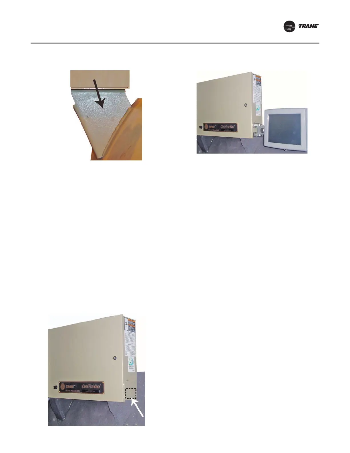
Alternative mounting location:
If the control panel mounting brackets are obstructed by
thick layers of insulation, electrical conduits, etc., such that
it is not possible to effectively install the display arm in the
recommended mounting location, it is permissible to
mount the display arm onto the side of the control panel
enclosure as shown in the below figures.
It is preferable to secure the
arm to the right-hand end of
the control panel enclosure, which is at the opposite end
of the cabinet from the door hinges. However, if a specific
retrofit situation makes it necessary to mount the display
arm on the left-hand end of the enclosure, please note that
all of the cables provided within the display upgrade kit are
long enough to allow this installation location to be
utilized.
If an alternative mounting location is chosen, please be
sure
to take
all of the precautions necessary to ensure that
no electrical components inside the control panel
Mounting Display Arm
Note:
• If utilizing the alternative mounting location, before
drilling the display arm mounting holes through the
side of the control enclosure, the following steps must
be taken to prevent damaging any of the electrical
components inside of the enclosure:
– Carefully position the template to ensure tha
t
all 4
mounting holes will be located such that the
installed mounting bolts will not come into contact
with any of the electrical components.
– Before drilling, ensure that all electrical
com
p
onents are adequately protected from metal
filings. Temporarily remove components if
necessary. Failure to prevent metal filings from
lodging against or inside of these electrical
components can cause them to fail when they are
re-energized.
– Before and during drilling, ensure that all e
lectrical
cables and wires are not in line with the path of the
drill bit. Failure to prevent damage to these
components can cause electrical shorts and/or
sparks to occur when the system is re-energized.
– After all 4 mounting holes
are drilled, use an
electronics vacuum to remove any dirt, debris, or
metal filings that may have accumulated inside of
the control enclosure.Be sure to properly reinstall
any components that were temporarily removed for
their protection during the drilling process.
1. Using the template provided, mark
the location
of the
4 mounting holes required on the chosen mounting
bracket.
2. Use a 3/8-inch bit to drill the holes.
Figure 16. Recommended mounting location on right-
ha
nd
control panel bracket
Figure 17. Alternative mounting location chosen due to
retrofitted insulation layers
Figure 18. Arm/display assembly mounted at
alternative location
 Loading...


