Installation
CDUB-SVN001B-EN 17
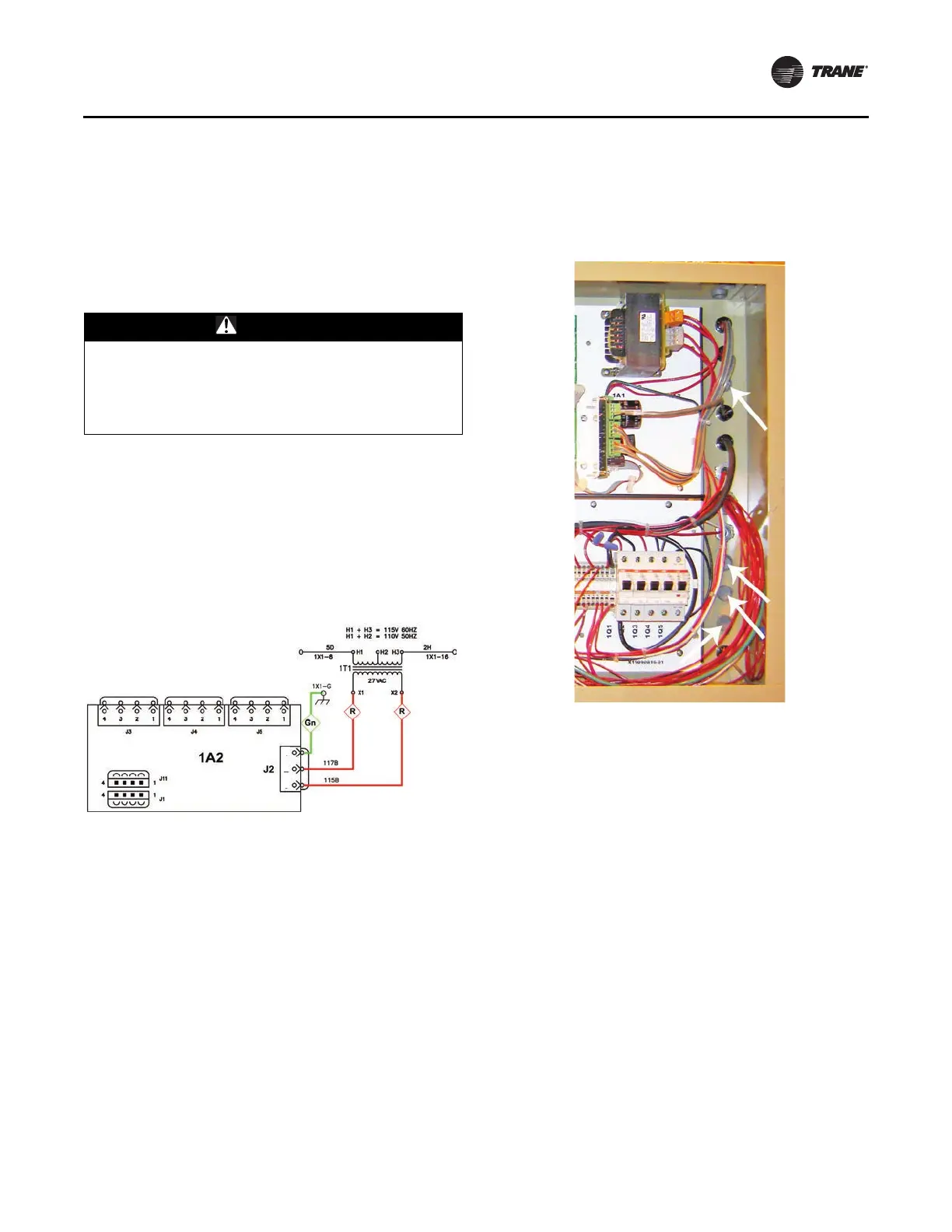
Connect Input Power Wiring to 1A2 Power
Supply
Notes:
• Proceed directly to the next
stage of the installation
process if the 1A2 power supply was already in place
as part of the previous CH530 control system.
• The full schematic wiring diagram can be found in
Figure 69, p. 35 of this manual.
1. Attach a Red 16 AWG wire between J2-1 on the 1A2
power supply and 1T1-X2.
2. Attach a Red 16 AWG wire between J2-2 on the 1A2
power supply and 1T1-X1.
3. Attach a Green 16 AWG wire between J2-3 on the 1A2
power supply and any availabl
e ground terminal on
the 1X1 terminal block.
Notes:
• Gn Green wire
• R Red wire
Routing New Wire Into and Out of the
Control Panel Enclosure
• Make use of the spare factory knock-outs that are
available on the right-hand end of the control
enclosure, for routing all required wiring runs from the
Symbio 800 controller and the 1A2 power supply out to
the connection points on the display.
• Plastic grommets are provide
d
in the upgrade kit to
line the edges of the knock-outs used.
Note: If a specific retrofit situation
has made it necessary
to mount the display arm on the left-hand panel
bracket or the left-hand end of the enclosure,
please note that all of the cables provided within
the display upgrade kit are long enough to allow
utilizing the spare factory knock-outs that already
exist on the back of the control panel enclosure.
Wiring Connections to the Display and
Symbio 800 Controller
Note: Also refer to the full schematic wiring diagram
located in Figure 69, p. 35 of this manual.
1. Ethernet communication cabl
e installation:
a. Attach the head of the Ethernet cable to the
display.
b. Route the cable through the wire channel on the
display arm.
Important: L
eav
e enough slack in the cable to allow the
display arm to be moved through its full
range of motion without placing a strain on
the cable or the terminal connections.
c. Take the cable around the
back side of the
control
enclosure and feed it into the cabinet through one
of the spare factory provided cable knock-outs.
d. Insert the cable end into the Ethernet port on the
Symb
io
800 controller.
WARNING
Ground Wire!
All field-installed wiring must be completed by qualified
personnel. All field-installed wiring must comply with
NEC and applicable local codes. Failure to follow this
instruction could result in death or serious injuries.
Figure 26. Input power wiring to the 1A2 power supply
Figure 27. Example of pre-existing spare factory knock-
outs on control enclosure
 Loading...


