Installation
18 CDUB-SVN001B-EN
2. Install the Female connector to stripped end wire
harness extension to the 1A2 power supply (the first
half of the power supply run to the display):
a. Route the stripped end of this wire harness through
the same
cabinet
knock-out used for the Ethernet
cable if possible, otherwise use one of the other
spare factory made knock-outs provided.
b. Connect each of the four individual
wires to the
corre
ct terminal of the removable J4 terminal plug
on the 1A2 power supply.
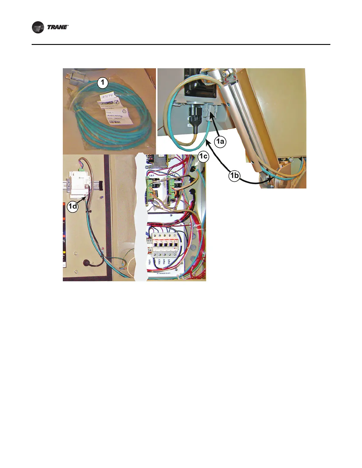
Figure 28. Ethernet cable installation betw
een the display and Symbio 800 controller
 Loading...


