Installation
20 CDUB-SVN001B-EN
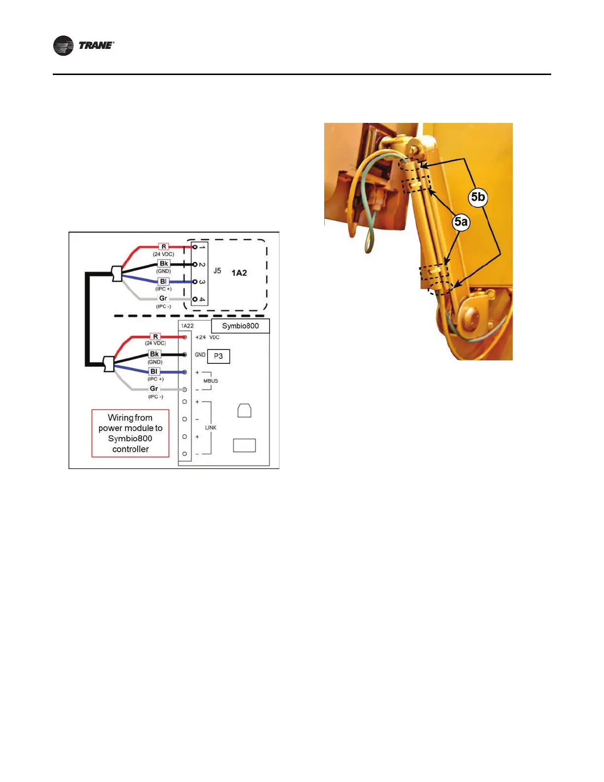
4. Connect the Symbio 800 controller to the 1A2 power
supply using the length of 4-conductor cable provided:
a. Connect each of the 4 individual wires on one end
of
the cable to the
correct terminal of the removable
J5 terminal plug on the 1A2 power supply.
b. Route the other end of the cable inside of the
cabine
t over to the Symbio 800 controller and
connect each of the 4 individual wires to the correct
terminals on the controller.
Notes:
• R. Red wire for 24 V
olts direct current
• Bk. Black wire for ground
• Bl. Blue wi
re for IPC+ connection
• Gr. Gray wire for IPC-connection
5.
Secure all cables in the wire
channel on the display arm
with cable ties:
There are 2 factory-drilled holes provided
in the wire
channel to aid in neatly securing the cables with cable
ties as is recommended.
Important: Wir
e
protection may be required at both
ends of the wire channel and at the door
hinge opening on the control panel
enclosure due to the potential presence of
sharp edges that could abrade or cut the
wires.
6. Use cable ties to clean up and secu
re wiring runs inside
of the control panel enclosure.
Solid State Oil Heater Relay
Installation
Note: This procedure does not apply to new chillers
operating with R514A refrigerant. Chillers with
R514A refrigerant have solid-state relay for heater
control installed and configured by the factory.
Relay RLY02909 is provided for
upgr
ading chillers with R-
123 refrigerant. This relay will operate with a 120V 15mA
signal, yet it will safely and quickly switch 120V loads up
to 25 amps. The oil heater’s amp draw is 6.25 amps at
120V, which is well within the capacity of RLY02909.
Mounting Location
The RLY02909 must be mounted directly onto a flat steel
face of the control panel, either on a side wall of the
enclosure, or on the back-plane panel. The mounting
surface acts as a heat sink for the relay, so the relay should
be securely bolted to the mounting surface.
Note: Ins
tructions included with the relay may require
removal of paint from the mounting surface, and
the use of a heat conductive paste between the
relay and the mounting surface. Trane’s lab testing
indicates that these additional steps are not needed
for the low 6 or 7 amp draw that our heater will
apply to the relay. Securely mounting the relay to
any steel surface in the control panel is adequate
for our application.
Figure 31. Wire connections from 1A2 power supply J5
to Sym
bio 800 controller
Figure 32. Neatly secure and protect cables in display
arm wire channel
 Loading...


