Installation
16 CDUB-SVN001B-EN
Install Quad Relay Output LLID—CH530 If
Using Chiller Control Sequence 1
Notes:
• If the DynaView had CTV
software and was using
control sequence 1, then installing the quad relay
output LLID is required. To determine this, examine the
chiller service report that was saved earlier. In the
configuration section, look for "Connected to" and in
the CH530 section, look for "Control Sequence". If
these items are “CTV” and “1”, respectively, then
adding the quad relay output LLID is required. If not,
then skip this procedure.
• If the quad relay output LLID is added, it also ne
eds to
b
e bound in the programming phase of the Symbio™
800.
1. Remove LLIDs 1A3 dual relay, 1A5
dual
relay, and 1A10
dual relay output from the control panel. Refer to
Figure 67, p. 33.
2. Install the quad relay output LLID in a
n open space in
the control panel, as close as possible to where the 1A3
LLID was formerly located.
Note: Th
is may also require moving some of the other
LLIDs to different
control panel locations.
3. Connect the wires from the prev
iously r
emoved LLIDs
to the quad relay output LLID terminals as shown in
Figure 67, p. 33.
Install Communication Cable Between
1A1 and 1A2 Power Supplies
Note: Proceed directly to the installation section
“Routing New Wire Into and Out of the Control
Panel Enclosure,” p. 17, if the 1A2 power supply
was already in place as part of the previous CH530
control system.
1. Connect the power supplies together at
the J1
terminals using the 2-conductor power supply
communication cable provided.
Note: If the J1 ter
m
inals are already being used, the
communication cable can instead be connected
to the J11 terminals on both power supplies.
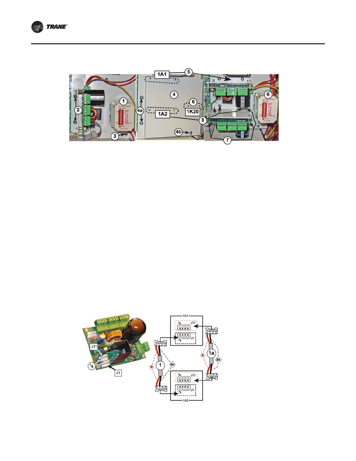
Notes:
• Bk - Black wire
• R - Red wire
Figure 24
. Installation of 1A2 power supply
Figure 25. Communication cable install between 1A1 and 1A2 power supplies
 Loading...


