Getting Started
8 CDUB-SVN001B-EN
Notes:
• Bk Black w
ire
• R Red wire
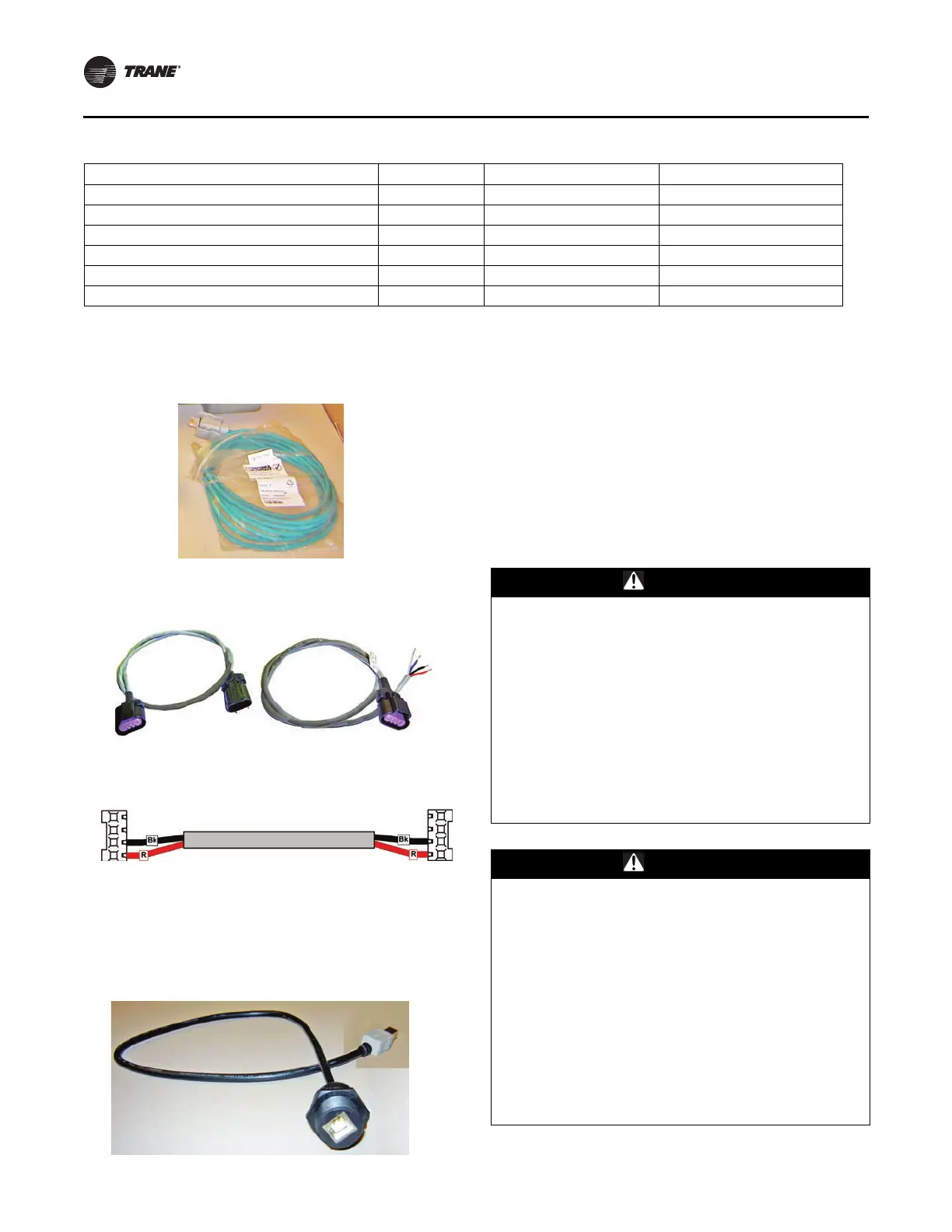
Fi
gure 5. USB Type B service port cable
Running the IPC Bus
There are several ways to string the IPC communication
bus on the chiller. The Symbio™ 800 AdaptiView display
upgrade kit includes a general wire kit that has several
different types of wires. An example of a wiring layout can
be seen in the below figure. Each application will vary
depending on the options. You may have extra cables, or
may be short needed cables. Extra cables can be ordered
through your local Trane Parts Center. Use the latest
version of PART-SVB16*-EN (Tracer CH530/CH531
Pluggable Connector System) for identification of
individual cables.
WARNING
Hazardous Voltage w/Capacitors!
Failure to disconnect power and discharge capacitors
before servicing could result in death or serious injury.
Disconnect all electric power, including remote
disconnects and discharge all motor start/run
capacitors before servicing. Follow proper lockout/
tagout procedures to ensure the power cannot be
inadvertently energized. For variable frequency drives
or other energy storing components provided by Trane
or others, refer to the appropriate manufacturer’s
literature for allowable waiting periods for discharge of
capacitors. Verify with a CAT III or IV voltmeter rated
per NFPA 70E that all capacitors have discharged.
WARNING
PPE for Electric Contact and Arc/Flash
Required!
Failure to disconnect power and discharge capacitors
before servicing could result in death or serious injury.
Disconnect all electric power, including remote
disconnects and discharge all motor start/run
capacitors before servicing. Follow proper lockout/
tagout procedures to ensure the power cannot be
inadvertently energized. For variable frequency drives
or other energy storing components provided by Trane
or others, refer to the appropriate manufacturer’s
literature for allowable waiting periods for discharge of
capacitors. Verify with a CAT III or IV voltmeter rated
per NFPA 70E that all capacitors have discharged.
Bracket; AdaptiView display Mt. 1 X05010050010 BRK04345
Hex HD screw; 7/16-20*1 3 42250080710
Lockwasher, Helical spring; 7/16 3 X22020026060
Normar size flatwasher; 7/16 3 X22050232150
Nut Hex; 7/16-20 3 X28020003110
Door assembly 1 506898140100
Figure 2. Ethernet cable for Symbio 800 controller to
display connection
Figure 3. Wire harness extensions: M to F connectors
and F connecto
r to stripped
Figure 4. Two-conductor power supply
comm
unication cable
(a) All part number information in this table is subject to change at any time.
Table 1. Basic bill of material for Symbio™ 800 control upgrade kit (continued)
Description Qty. Part Number
(a)
Mnemonic Part Number(a)
 Loading...


