Installation
14 CDUB-SVN001B-EN
.
3. Secure the arm to the control panel bracket using the
5/16 - 18 x 1-inch hex bolts, 5/16 - inch lock washers, and
5/16 - 18 hex nuts provided. Note that included
production arm bracket can also be bolted to panel
mounting bracket.
4. Securely fasten the Tracer AdaptiView display to the
m
ounting plate on the end of the display arm with the
hardware provided.
5. After the display is attached, recheck the arm tension.
The arm tension should be set so that the display does
not spring up or sag down out of the position it is
moved to by the operator.
Adjusting the Tracer AdaptiView Display
Arm
The Tracer AdaptiView display arm may be too loose or
too tight and in need of adjustment. To adjust the tension
on the display arm:
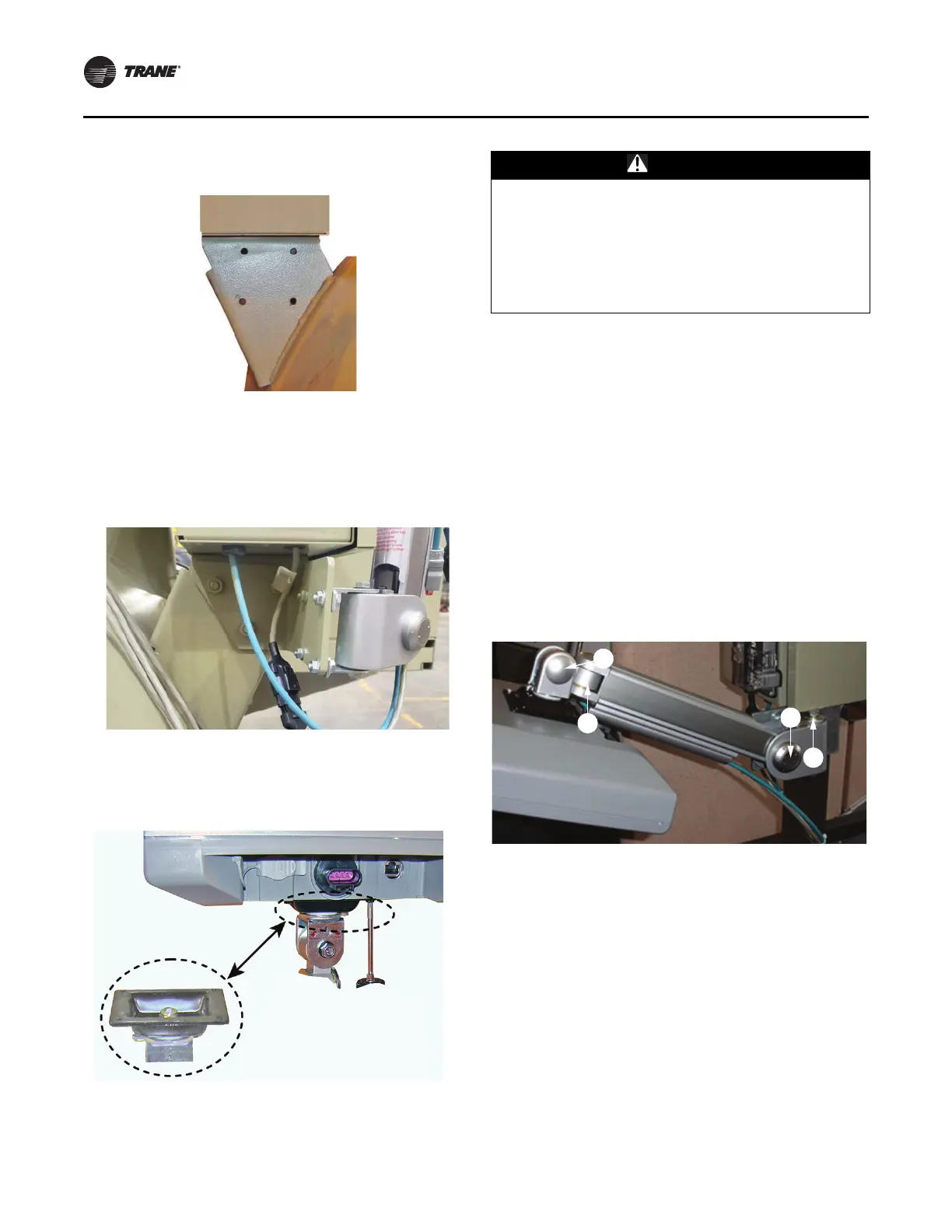
1. There are three joints on the display arm
that allow the
Tracer AdaptiView display to be positioned at a variety
of heights and angles (refer to items labeled 1, 2, and
3 in the below figure). At each joint in the display arm
there is either a hex bolt (1 and 2) or hex screw (3). Turn
the hex bolt or screw in the proper direction to increase
or decrease tension.
Note: Each hex
bolt or screw is labeled with ‘loosen’/
‘tighten’, or '+'/'–' indicators.
2. Joint 3 has a 6 mm hex screw controlling the tension on
a gas
spring, which allows the Tracer AdaptiView
display to tilt up and down.
3. Joints 1 and 2 are covered by a plastic cap. Remove the
plastic cap to access the hex
bolt. Adjust using a 13 mm
wrench as
necessary.
4. To adjust the swivel of the T
racer AdaptiView display
(the spin right and left similar to the steering wheel on
a car), you need to adjust the hex bolt located inside the
display arm back plate. This adjustment needs to be
done BEFORE attaching the display. Use a 9/16-inch or
14 mm wrench.
5. Use a 13 mm wrench to adjust the
bolt (item labeled 4
in the above figure) that allows the entire display arm
to swivel to the left and right.
Figure 19. Display arm mounting holes drilled through
right-hand panel bracket
Figure 20. Production arm bracket
Figure 21. Attaching Tracer AdaptiView display to arm
CAUTION
Tension in Display Support Arm!
Failure to follow instructions below could result in
unexpected movement of the spring-loaded support
arm which could result in minor to moderate injury.
Ensure that the support arm is in the full upright
position when removing the Tracer AdaptiView display
from the support arm.
Figure 22. Joint locations on the display arm
 Loading...


