Installation
CDUB-SVN001B-EN 15
Install Power Supplies and
Hardware
Install 1A2 Power Supply—CH530 If Not
Already Present
Note: Proceed directly to the next stage of the installation
process:
• for
CH531 applications, or
• If there are already two power supplies (1A1 and
1A2) in place from the previous CH530 control
system.
1. Find the factory-drilled mounting holes on the inner
b
a
ck wall of the control panel enclosure to the right of
the existing power supply.
2. Attach the power supply to the mounting bracket w
ith
the hardware provided.
3. Attach the power supply as
sembly to the back w
all of
the enclosure using the 10-32 x 0.50-inch screws
provided.
Note: In all subsequent manual pages, this new power
su
pply will be referred to as the 1A2 power supply,
while the preexisting power supply from the
original control system will be referred to as the
1A1 power supply.
Install 1A2 Power Supply - CH531 Prebuilt
Panels
1. Locate and remove the vent line solenoid time delay
relay and base.
Note: Do not unwire the base. The wires should be
lon
g enough to reach the new location. Use
caution when removing the timer because the
center alignment post is very fragile.
2. Locate and remove the 1A1 power supply LLID and
bracket.
Note: D
o not unwire the 1A1 power supply LLID. The
wi
res should be long enough to reach the new
location.
3. Locate and remove the middle back panel securing
screw
on the right side.
4. Install the new sub back panel provided with the kit.
a. Secure the left side of the bracket using two #10-32
by
1/2-inch screws and the holes emptied by the
removal of the power supply bracket.
b. Secure the right side of the bra
cket using one 10-32
x 1.00-inch screw and the hole emptied by the
removal of the back panel securing screw.
5. Using the screws that were removed in Step 2, attach
the existing powe
r supply LLID
onto the new panel in
the holes labeled 1A1.
6. Using the screws that were removed in Step 1, attach
the vent
li
ne solenoid time delay relay and base in the
holes labeled 1K20.
Important: The tim
er must be aligned correctly with the
base.
7. With the hardware provided, attach
the new power
su
pply to the mounting bracket.
8. Using 10-32 x 0.50-inch screw
s provided, attach the
power supply assembly to the new panel in the holes
labeled 1A2.
Note: In
all subsequent manual pages, this new power
supply
will be referred to as the 1A2 power supply,
while the preexisting power supply from the
original control system will be referred to as the
1A1 power supply.
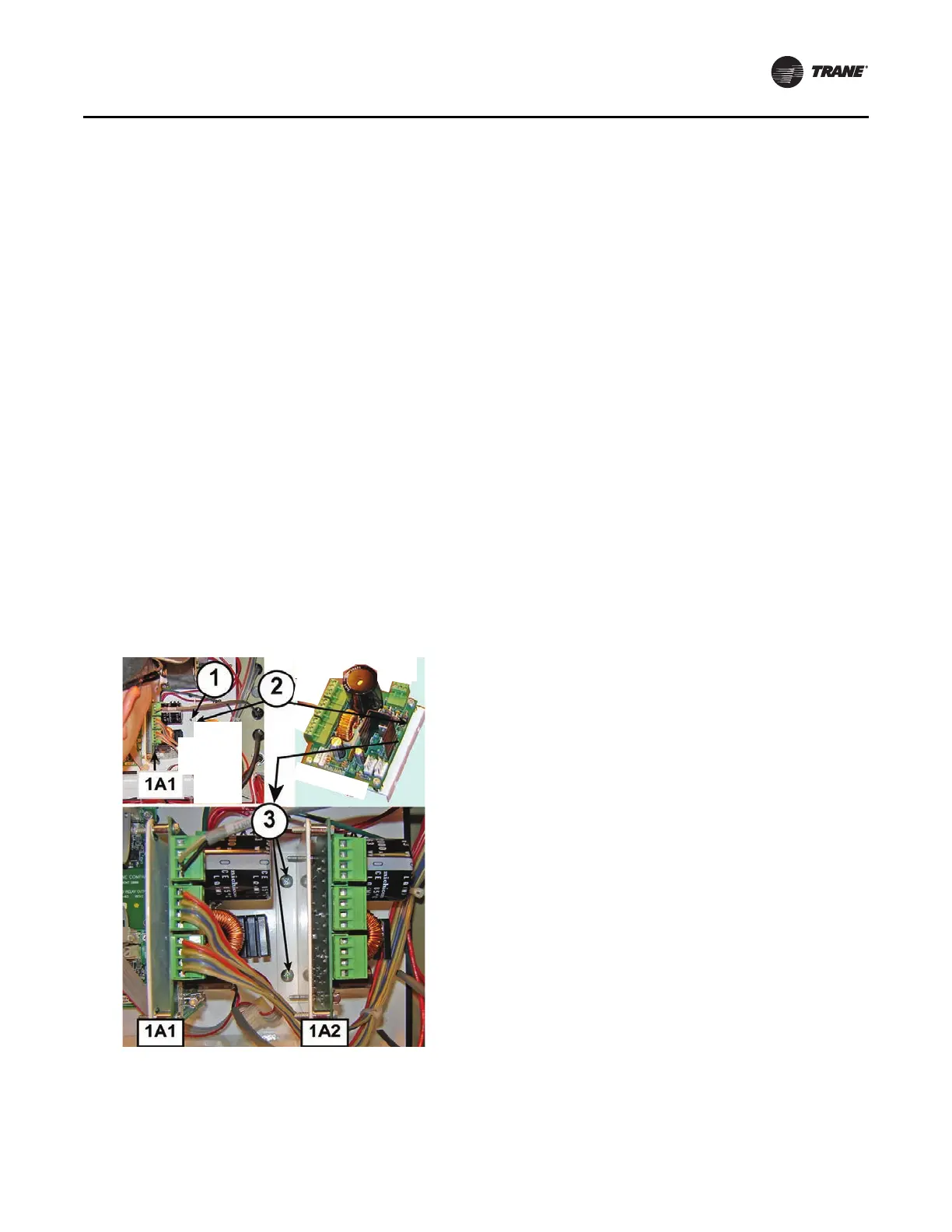
Figure 23. Installation of second power supply
 Loading...


