Wiring Diagrams
CDUB-SVN001B-EN 35
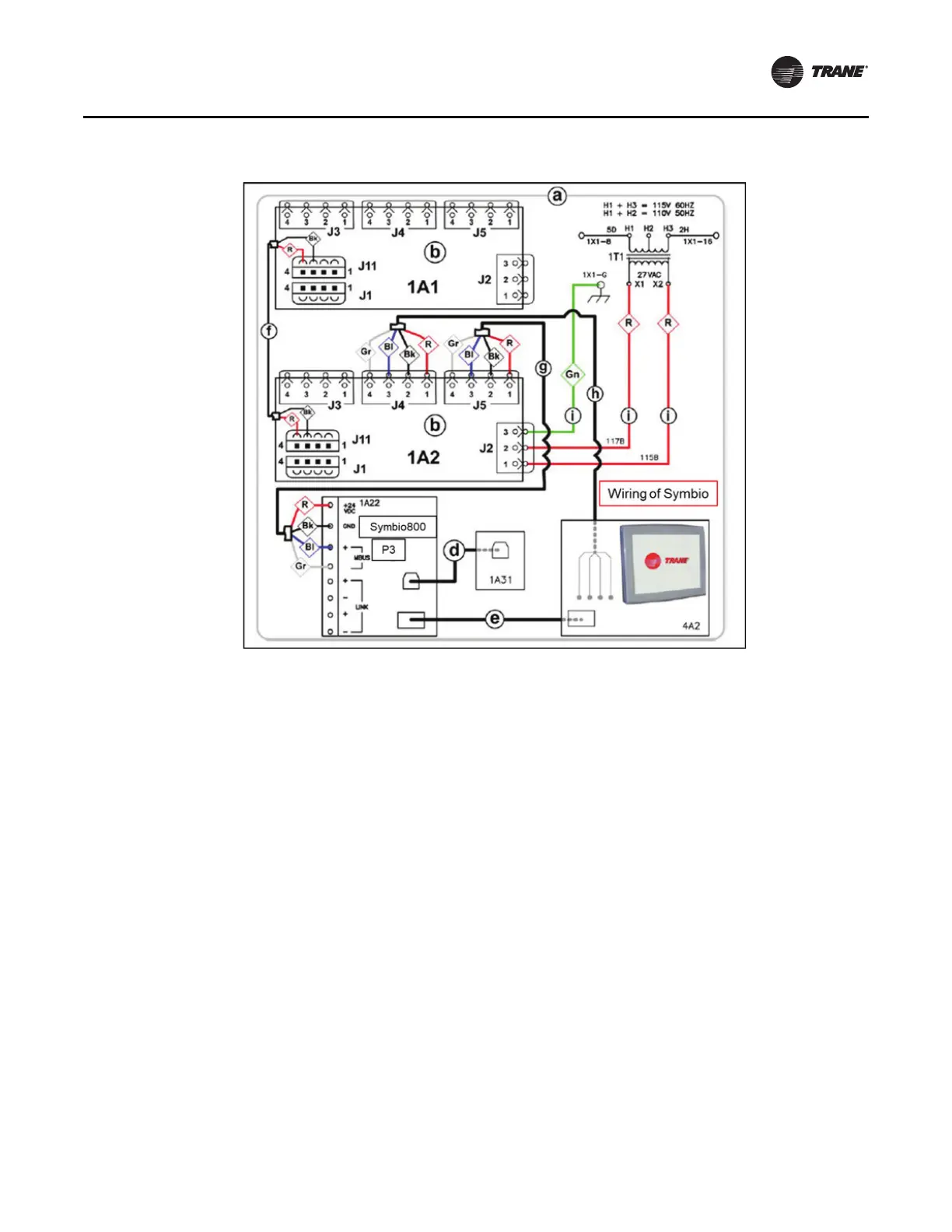
Notes:
•a - All notes and hazard notifications listed in “Wiri
ng
Diagrams,” p. 32 of this manual apply to this drawing
•b - Power Supply
•c - Symb
io 800 controller
•d - USB Type B service port cable from Symbio 800
con
troller receptacle to control panel door
•e - Ethernet cable connection between Symbio 800
Ethernet port and Symbio 800 display
•f - 2-conductor communication cable (It could also be
connected between J1 terminals)
•g - 4-conductor cable
•h
- Female to bare end wire harness to Male to Female
wire harness extension to display
•i - Field provided
16 AWG control wire
•Bl - Blue wire
•Bk - Black wire
•G
n - Green wire
•Gr - Gray wire
Figure 69. Full schematic wiring diagram for a standard Symbio 800 upgrade kit
 Loading...


