Wiring Diagrams
34 CDUB-SVN001B-EN
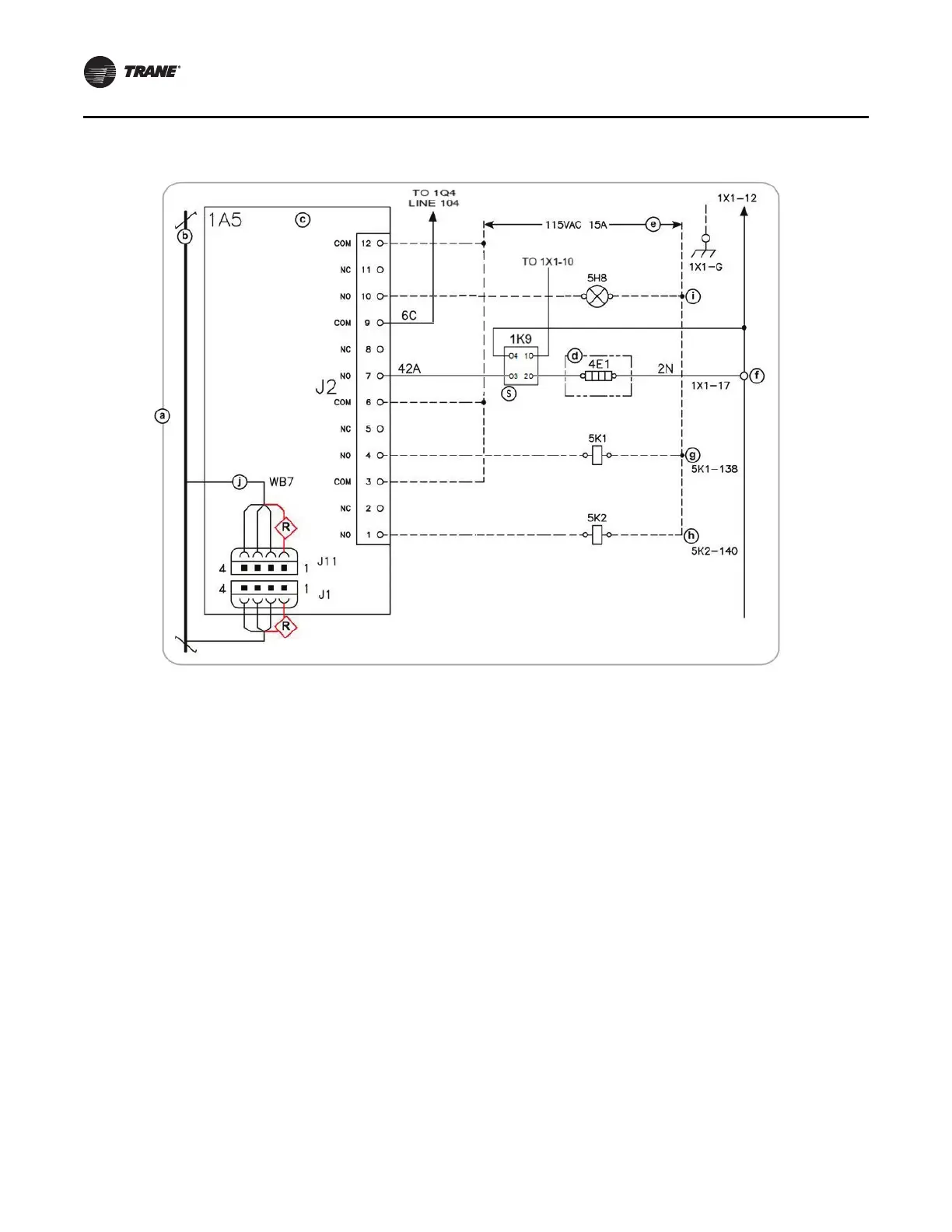
Notes:
•a - All notes and hazard notifications listed in “Wiri
ng
Diagrams,” p. 32 of this manual apply to this drawing
•b - IPC BUS
•c - Quad re
lay output
•d - Oil tank junction box
•e - Customer provided
•f
- Oil tank heater
•g - Evaporator water pump (optional)
•h
- Condenser water pump (required)
•i - Ice building indicator (optional)
•j - WB7 connects to 1A4-J11 (Line 101) when 1A4 is
pr
esent
•R - Red wire (proper orientation of connector for
plugging into this terminal block is with the connector
end terminal holding the red wire being lined up with
block terminal number 1)
•S - Solid state oil heater relay
Figure 68
. Quad relay LLID installation
 Loading...


