3
INSTALLING THE FORK AND HANDLEBAR
IF YOU DO NOT NEED TO CUT THE FORK,
GO TO STEP 3.
Cutting the fork
(
Steps 2.1–2.4
)
It is necessary to install the fork, heat set assembly
and stem together in order to get the correct location
for cutting the steerer.
2.1 Holding the fork legs, slide the stem down the
steerer until it is firmly seated on top of the
bearing top cap or shaped spacers.
Lightly tighten the stem clamp bolts.
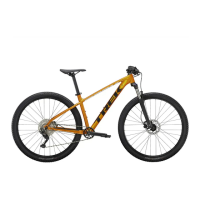
2.2 Determine the preferred cut
length. Use additional spacers
above the stem until you are
certain about the desired
stack height (handlebar
height). Mark a fine line
on the flat side of the
steerer along the top
edge of the stem.
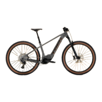
2.3 If you are planning to use the 5mm spacer recessed
in the stem, your actual cutting line should be 5mm
below the pencil mark made in Step 2.2. If you are
planning on using a 5mm headset spacer above the
stem, cut on the line.
5mm
IMPORTANT
There is a 5mm spacer built into the stem which allows
you to install the stem top cap flush with the stem.
2.4 Proceed with cutting the steerer at the selected
location from step 2.3 using a standard carbon
steerer cutting process.
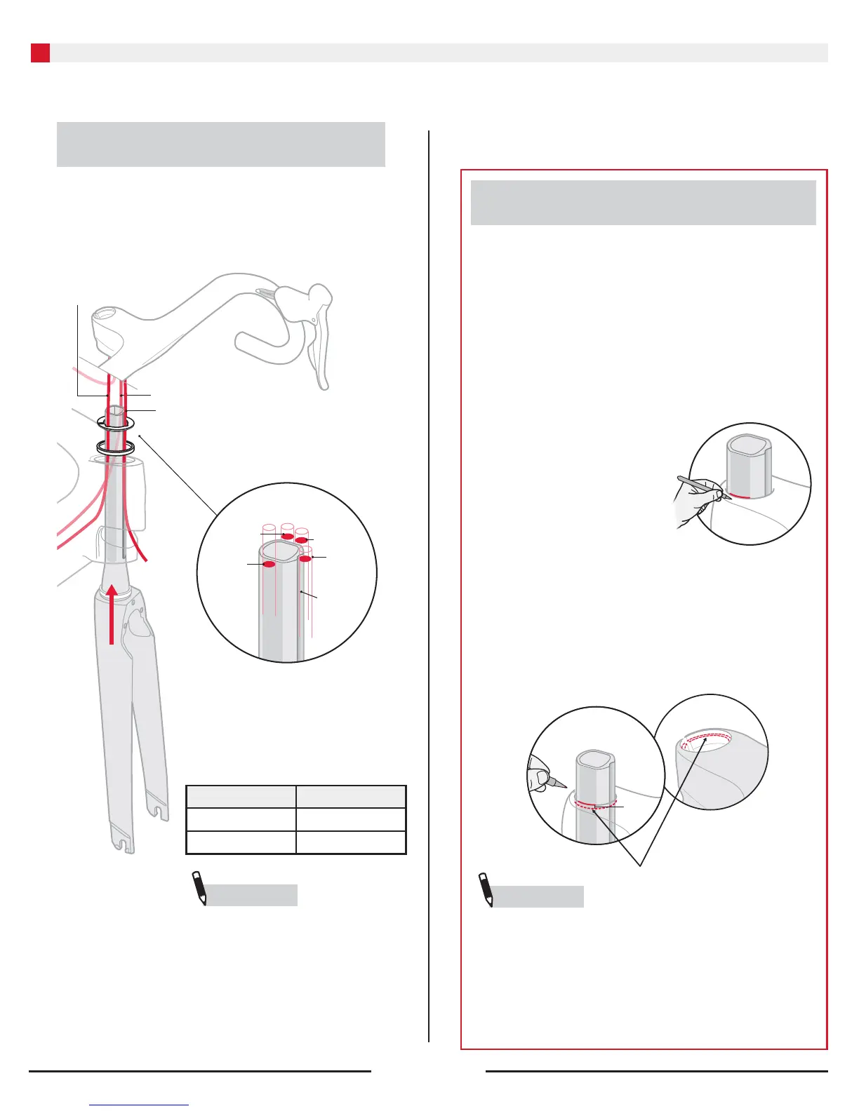
Installing the fork
1. While you guide the housings to the correct sides
of the steerer (see Steerer diagram), pass the
fork through the head tube, upper bearing,
compression ring, spacers, and the stem.
FRONT
DERAILLEUR
FD
RB
RD
FB
FRONT
BRAKE
REAR
DERAILLEUR
Steerer diagram
STEERER
“FLAT” NON-DRIVE SIDE
“GROOVE”
FACES
FRONT
“FLAT” DRIVE SIDE
Non-drive side Drive side
Rear brake Front derailleur
Rear derailleur
Sides of steerer and cable locations
IMPORTANT
The front brake housing sits in the
groove at the front of the steerer.
2.3
10