CIRCUIT
DESCRIPTION
The output
of IC6 is
used
to
drive
an LED and as a
control
signal
for
blanking
and
sweep switching.
The
operation
of
the trigger mode switch input
is the
same
as for the
horizon-
tal display switch group. Diodes D13-D16
and IC1a and
IC1b
are
used
to
encode
2
bits
of
switch status information
for this switch group after pulse shaping
is
done.
D1 7, D18
IC2a,
IC2b, IC2f
and
IC3a determine whether
an
input
is
present, writing into
the
register IC7a
and
IC7b
the ap-
propriate status information.
This register holds
the
switch status encoded information
until
IC8 is
used
to
cancel,
or
return
the
status information
based
on
alternate operation
of the
switches. Similar
to the
horizontal display switch group, once depressed
a
switch
mode
is
maintained until
the
switch
is
depressed once
more.
IC5a, IC5b,
and
IC5c
are
tri-state buffers. IC9a,
IC9b,
and
IC9d —IC9f along with
Q1 -Q3
form buffers
for
the switch LED's
and
sweep circuit.
The
output from
the
trigger mode reset switch
is
pulse shaped
and
sent
to the
trigger sweep circuit.
This circuit holds data even when
the
instrument's power
supply switch
is
turned
OFF.
That control
is
performed
by
Q4,
D19, D20, IC3 and
IC8a.
D19
and D20
form
a
power supply based
on the
internal
lithium battery
for
memory backup. IC3b
and
IC3c detect
the power
OFF
condition
and
generate
a
memory save
signal.
The
output
of the
above circuit forms
the set of
con-
trol signals used
to
control
the
vertical mode logic circuitry.
CALIBRATING VOLTAGE CIRCUIT
Q11
and Q12
form
a
multivibrator circuit which generates
a
signal which
is
subsequently converted
to a low
impedance
by means
of Q10 for
output
as the
calibration signal.
It is
also used
for
creation
of a
current calibration signal
by
means
of R70 and R71. The
current calibration signal
is
output
via a
rear panel terminal.
IC17 is
used
to
regulate
the
voltage generated
by
this calibration circuit.
CH3
and CH4
INPUT CIRCUITS
These circuits consist
of an
attenuator
and
buffer amplifier.
Q16 drives
a
relay
to
switch
the
attenuation between
1/1
and
1/10. The
signal from
the
attenuator
is
impedance
con-
verted with
the
circuit formed
by
Q13a,
Q13b, Q14 and Q15
and sent
to the
vertical pre-amplifier.
The
operation
and
configuration
of the CH4
circuit
is
similar
to the CH3
circuit.
HORIZONTAL OUTPUT AMPLIFIER
The signal from
the
horizontal sweep circuit
is
amplified
by
the differential amplifier formed
by Q1 and Q2. The
output
signal
of
this circuit
is
then passed
to the
emitter follower
circuit formed
by Q5 and Q6 for
impedance conversion
to
enable driving
the
circuit formed
by Q7 and Q8. Q9 and
Q10 form
a
voltage regulation circuit which serves
as the
DC load
for Q7 and Q8
respectively with
AC
peaking per-
formed
by
means
of C15 and C16. Q11 and Q12
form
an
auto-bias circuit which automatically controls
the
operating
point
of the
output stage.
It
also serves
as the
beam finder
circuit such that when
the
base
of Q13 is
grounded
the
operating point
of the
output stage
is
lowered, resulting
in a
shrunken display.
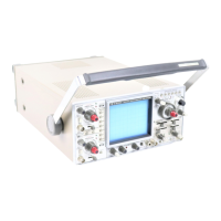
SWITCHING POWER SUPPLY UNIT
Although
the
CS-2100A
is
light
and
compact
and
make
use
of
a
switching regulator type power supply.
Input
of
either
100V of
200V
is
rectified
and a
smoothing
capacitor
is
used
to
generate
a
smooth
DC
output
of ap-
proximately 200V.
Next,
a
power transistor
is
used
to
convert this output
to an
AC voltage which
is
used
to
drive
a
compact type converter
transformer.
The
transformer used
has 6
bifilar windings
which create
six
separate outputs which
are
then rectified
and smoothed
to
provide
the
supply
for the
blanking unit
directly.
One of the
outputs
is
compared with
a
reference
voltage
to
form
an
error voltage used
for
regulation.
The
error voltage
is
sent
to the
error voltage amplifier,
the
output
of which
is
used
to
control
the
base
of the
power transistor.
This output
is
isolated from
the
primary
by
means
of a
photocoupler.
POWER BLANKING UNIT
The five remaining outputs from
the
switching regulator
power supply
are
further regulated using
a
series regulation
method.
This accomplished with Q1.Q3 —Q6.
IC1a, IC1b,
IC2a
and
IC2b
are
error voltage amplifiers.
The + 20V
deriv-
ed
by use of a
resistance voltage divider.
A
conventional high
voltage DC-DC converter
is
used.
Q25
—Q27
are
error
voltage amplifiers with
Q29
acting
as a
control transistor.
The CS-2100A provides independent
A and B
sweep
intensity controls. This function
is
implemented
by
means
of
the circuit formed
by Q13
—Q15.
Q16
forms
the
beam
finder circuit which allows
the
beam
to be
seen even
if the
intensity control
has
been inadvertently turned
to
minimum.
Q17 forms
the
external intensity (Z-axis) modulation circuit
which accepts
an
input
and
results
in
brighter displays
for
increasing inputs.
The signals from these circuits
are
combined
at the
base
of
Q18
to
drive
Q19. Q20
forms
the DC
load
for Q19
with
C25 acting
to
provide
AC
peaking
for
this circuit.
Q21 and
Q22 form
the
auto-focus circuit which apply
a
signal
to the
focus electrodes
of a
reverse phase from
the
blanking signal.
Q23
and Q24 act to
restore
the DC
component
of the
blank-
ing
and
auto-focus circuits
by
using differential amplifiers
for
isolation.
Q8
controls scale illumination with
Q9 and Q10
controlling
the
adjustment
of
trace rotation.
Q11 and Q12
are used
to
adjust perpendicularity.
7-3