16
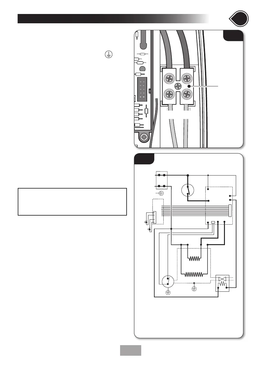
• Route the cable into the shower unit for
connection to the terminal block (fig.11)
as follows:
Earth cable to terminal marked
Neutral cable to terminal marked N
Live cable to terminal marked L
• Fig.12 shows a schematic wiring diagram.
IMPORTANT: When connecting the cable fully
tighten the terminal block screws and make sure
that no cable insulation is trapped under the
screws. Loose connections can result in cable
overheating.
NOTE: The supply cable earth conductor must
be sleeved. The outer sheath of the supply cable
must be stripped back to the minimum.
• The use of connections within the unit or
other points in the shower circuit to supply
power to other equipment i.e. extractor fans,
pumps, etc. will invalidate the guarantee.
• DO NOT switch on the electricity supply
until the shower cover has been fitted.
7
Continued
SECTIONSECTION
NOTE: The elements on UK models are to
240V specification and will give a lower kW
rating if the voltage supply is below 240V.
Fig.11
L
N
E
1
2
3
5
7
6
inlet
outlet
9
9
4
8
10
11
1. Terminal block
2. Earth post
3. Control PCB
4. Power PCB
5. Solenoid valve
6. Thermal cut-out
(main)
7. Thermal cut-out
(outlet)
8. Connector socket
9. Element
10. Power LED
11. Low Pressure LED
Fig.12

 Loading...