5.9.3.2
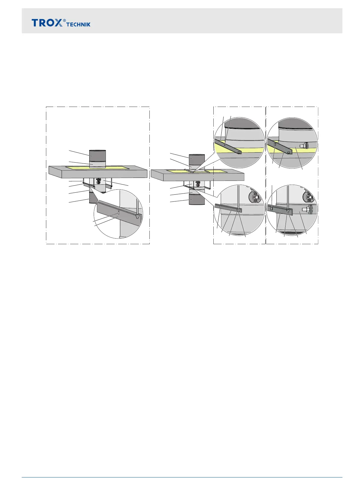
Vertical duct
Suspended installation of the fire damper
Suspension below the ceiling slab with solid brackets and rivets. Fig. 33/1)
Fixing above and below the ceiling slab with rivets. Fig. 33/2)
Fixing above and below the ceiling slab with heavy duty clamp. Fig. 33/3)
2)1) 3)
①
⑧
⑤
④
③
②
③
②
⑨
⑧
⑨
࿆
࿇
⑩
⑨
⑤
④
⑫
⑩
⑫
⑪
①
⑥
⑤
④
③
②
③
②
⑦
࿆
࿇
Fig. 33: Suspended installation variants for fire dampers
①
Fire damper
②
Extension piece
③
Flexible connector
④
Threaded rod, at least M8, galvanised steel
⑤
Washer and nut suitable for the threaded rod
⑥
4 steel rivets ∅ 6.4 mm, clamping range
2 to 20 mm, e.g. cap blind rivets or high strength
rivets. The riveted connection must be air-tight.
⑦
L-section to EN 10056-1 60 × 30 × 5 mm
⑧
Angle section 20 × 20 × 3 mm to EN 10056-1
⑨
4 steel rivets ∅ 6.4 mm clamping range
2 to 20 mm, e.g. cap blind rivets or high strength
rivets; the riveted connection must be air-tight.
⑩
Angle section 35 × 35 × 4 mm to EN 10056-1
⑪
Screw fixing suitable for the clamp
⑫
Clamp, e.g. Hilti MP-MX, Valraven BIS HD 500, or
equivalent
Ⓐ
Installation side
Ⓑ
Operating side
Installation
Suspended installation of the fire damper > Fire dampers with fire batt
Fire damper Type FKRS-EU 47