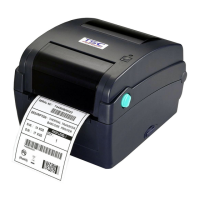
TTP-243 Pro/ 243E Pro/ 342 Pro
Bar Code Printer
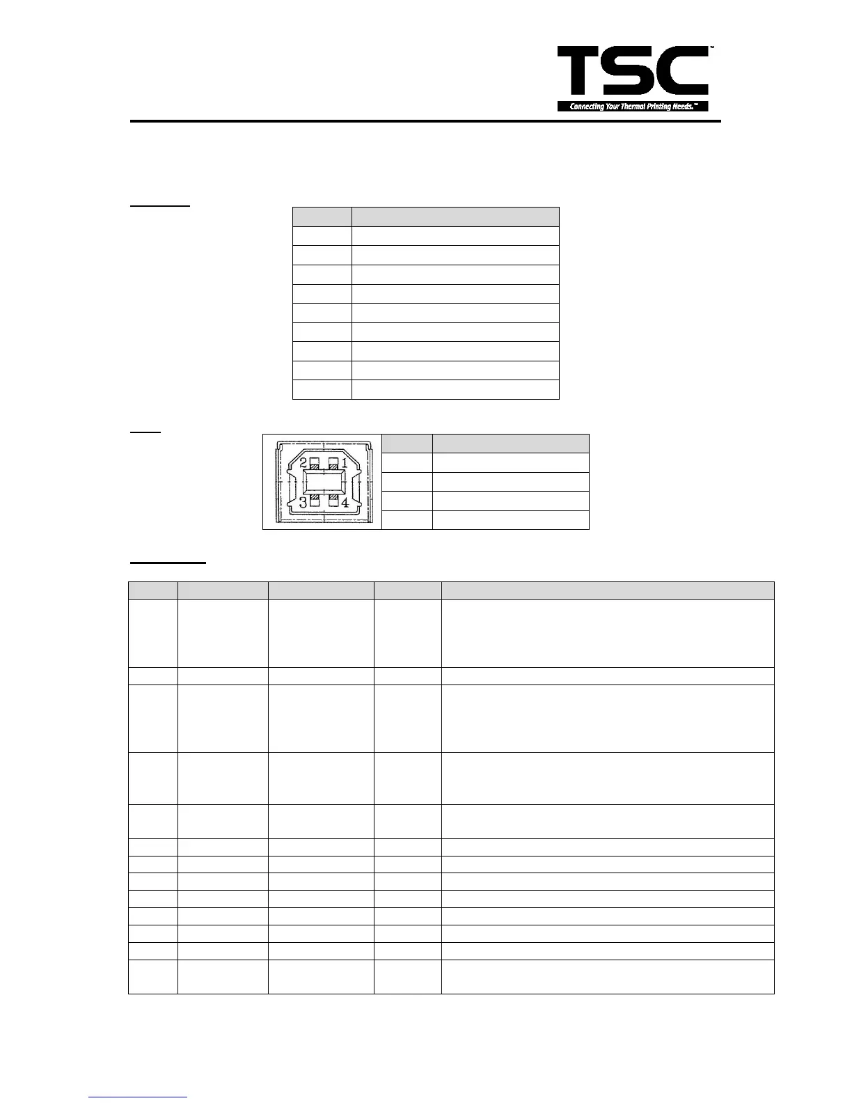
3.2 Pin Configuration
RS-232C
A low on this line indicates that there are valid data
at the host. When this pin is de-asserted, the +ve
clock edge should be used to shift the data into the
device.
Data Bus. Single-directional.
A low on this line indicates that there are valid data
at the Device. When this pin is de-asserted, the
+ve clock edge should be used to shift the data into
the host.
When in reverse direction, a high indicates data,
while a low indicates a command cycle. In forward
direction, it functions as PtrBusy.
When low, device acknowledges reverse request.
A low set by the device indicates that the reverse
data is available