EasyManuals Logo

TSC TTP-247 User Manual

TSC TTP-247
50 pages
To Next Page IconTo Next Page
To Previous Page IconTo Previous Page
Page #20 background imageLoading...
Page #20 background image
15
4. Use a screwdriver to screw off 6 screws on the lower inner cover.
Fig. 23 Remove 6 screws from lower inner cover
5. Place the printer upside down and unscrew the two screws of the hinge holder
on the lower cover.
6. Unscrew the screw of the memory card cover and remove the memory card
cover. Plug in the cutter driver IC at U14(TTP-245/343) / U30(TTP-245 Plus/343
Plus/247/345) socket on the main board.
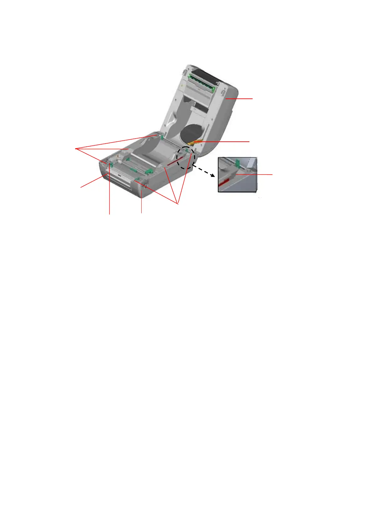
7. Use both thumbs to hold the lower cover and index fingers to lift up the top cover
open levers to separate the lower inner cover and the lower cover.
8. Arrange the cable through the bezel. Connect the cutter module cable to the
4-pin socket on printer PCB.
Screws
Top Cover
Screws
Top Cover Support
Flute
Lower Cover
Lower Inner Cover
Front Panel

Other manuals for TSC TTP-247

Questions and Answers:

Question and Answer IconNeed help?

Do you have a question about the TSC TTP-247 and is the answer not in the manual?

TSC TTP-247 Specifications

General IconGeneral
Print MethodThermal Transfer / Direct Thermal
Resolution203 dpi
Max Print Width4.09" (104 mm)
Processor32-bit RISC CPU
Weight2.5 kg
Max Print Speed7 ips
Memory8 MB SDRAM, 4 MB Flash
InterfaceUSB 2.0, Serial
Ribbon Capacity300 meters
Label Width1" (25.4 mm) ~ 4.33" (110 mm)
Label Thickness0.06 mm ~ 0.19 mm
Power SupplyExternal Universal Switching Power Supply
Operating Temperature5°C to 40°C (41°F to 104°F)
Storage Temperature-4°F to 140°F (-20°C to 60°C)
Operating Humidity25% to 85%, non-condensing
CertificationsCE, FCC, UL, CCC

Related product manuals