Service Manual
2.2 Interface Pin Configuration
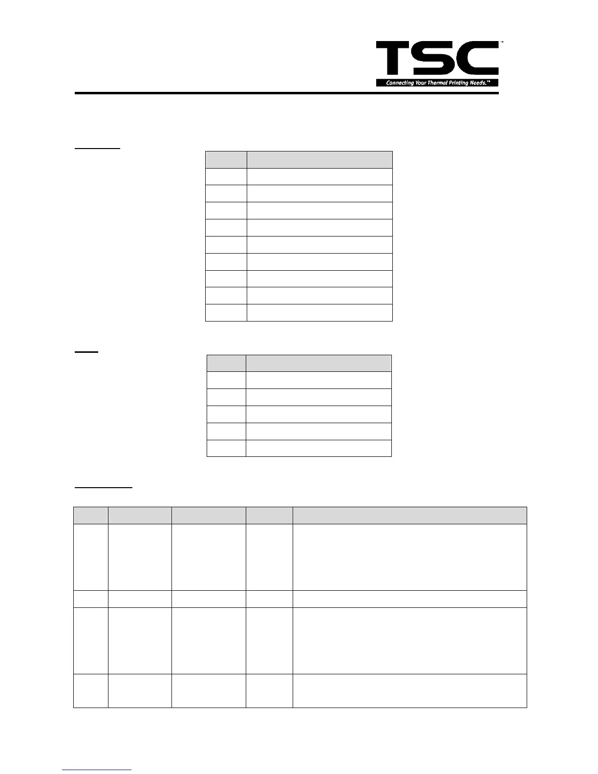
RS-232C
PIN CONFIGURATION
1 +5 V
2 TXD
3 RXD
4 CTS
5 GND
6 RTS
7 N/C
8 RTS
9 N/C
USB
PIN CONFIGURATION
1 +5 V
2 D-
3 D+
4 N/C
5 GND
Centronics
Pin SPP Mode Nibble In/Out Function
1 Strobe N/A In
A low on this line indicates that there are valid data
at the host. When this pin is de-asserted, the +ve
clock edge should be used to shift the data into the
device.
2-9 Data 0-7 N/A In Data Bus. Single-directional.
10 Ack N/A Out
A low on this line indicates that there are valid data
at the Device. When this pin is de-asserted, the +ve
clock edge should be used to shift the data into the
host.
11 Busy N/A Out
When in reverse direction, a high indicates data,
while a low indicates a command cycle. In forward