OVEN SYSTEMS
25
Testing a High-Voltage Diode
DANGER: Never attempt to measure high
voltage directly. Death or serious injury
could result.
1. Disconnect the oven from the power source.
2. Fully discharge the capacitors.
3. Connect the voltage meter in series with high-
voltage diode.
4. Using a multimeter set to DC voltage, connect
one meter lead to one side of a 9-volt battery
and the other lead to one side of the high-voltage
diode.
5. Connect the other side of the 9-volt battery to
the other side of the high-voltage diode. DC
voltage should be present on the meter in only
one direction.
6. Switch the meter leads on the high-voltage diode,
which will cause the opposite reading to be
visible. Depending on the voltage of the battery,
voltage between 5-7 VDC should be present in
only one direction and 0-0.1 VDC in the other
direction.
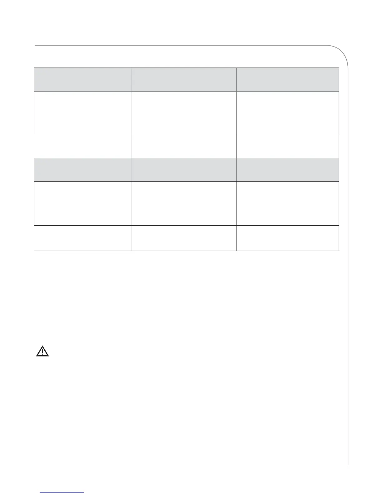
High Voltage Transformers Primary Voltage, Frequency, Taps,
and Resistance
Secondary Taps and Resistance
NGC-3062-1 208 VAC, 60 Hz, 1 & 2,
0.819–1.001 :
240 VAC, 60 Hz, 1 & 3,
0.972–1.188 :
4, Ground, 53.60–65.52 :
NGC-3062-2 230 VAC, 50 Hz, 1 & 2,
0.972–1.188 :
3, Ground, 57.52–70.30 :
Filament Transformers Primary Voltage, Frequency, Taps,
and Resistance
Secondary Taps and Resistance
NGC-3061-1 208 VAC, 60 Hz, 1 & 2,
17.49–21.37 :
240 VAC, 60 Hz, 1 & 3,
20.61–25.19 :
4, 5, very low resistance - if read-
ing is open, transformer has failed.
NGC-3061-2 230 VAC, 50 Hz, 1 & 2,
18.99–23.21 :
3, 4, very low resistance - if read-
ing is open, transformer has failed.
Figure 31: High Voltage and Filament Transformer Resistance Table

 Loading...