http://www.tyan.com
14
Chapter 2
Board Installation
Now that you have installed your IDE drives, your floppies are next.
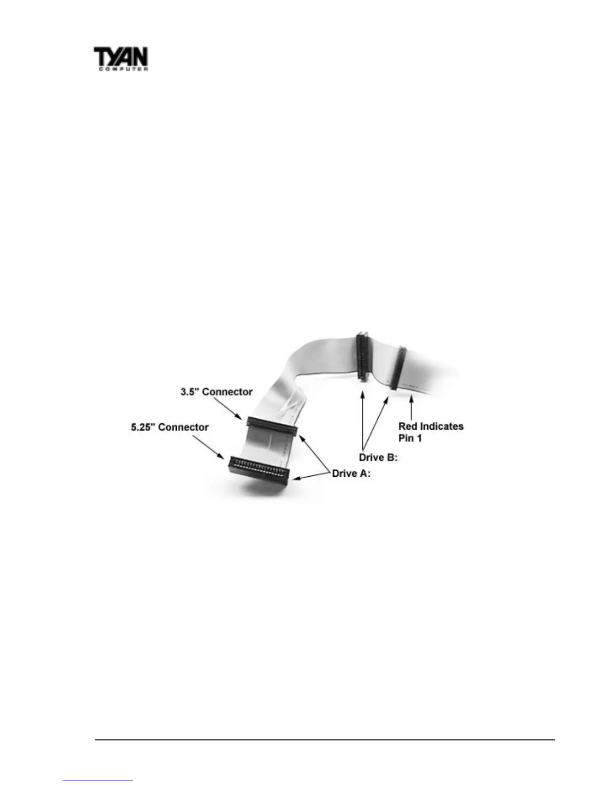
Pin 1 on the floppy cable is usually denoted by a red or colored stripe down
one side of the cable (see Figure 5). Most of the current floppy drives on the
market require that the colored stripe be positioned so that it is right next to
the power connector. In most cases, there will be a key pin on the cable which
will force you to connect the cable properly.
Drive A: is usually attached to the end of the cable with the twist in it. Drive B:
is usually connected to the middle of the cable. Refer to your installation
instructions or call your dealer if you are unsure about attaching floppy drives.
Refer to Figure 5 below for a detailed anatomy of the floppy cable. Remember,
you can only have two floppy drives connected at any given time.
Figure 5
The colored stripe on the cable indicating pin 1 should face towards the rear of
the case (towards the ATX connectors), as with the IDE cables. Please refer to
your documentation for proper installation, or see Figure 4 on page 13.
Some symptoms of incorrectly installed floppies are:
• Floppy drives are not detected: usually caused by faulty cables, backward
cables, or a bad floppy or motherboard. Try another single floppy drive to
verify the problem or try another cable. Also, check to see if the onboard
floppy is enabled in the BIOS.
• Floppy Drive Fail message at bootup: the cable, floppy, or motherboard
may be faulty. Try another cable or floppy drive to verify.
 Loading...