4 of 35 REF: CCU3/C-4100.DOC REV: M September 26, 2005
2. Before the Installation
This section describes how to physically install the CCU3/C-4100. Please see XL
Graphics document Site Configuration for further configuration details.
This equipment is designed for installation and servicing by fully qualified field
engineers. There are no user serviceable or installation parts inside.
2.1. Parts Supplied:
1 x CCU3/C board with firmware for Simplex Interface
1 x Mounting bracket (part#: CCUBRKT)
4 x M4 x 6 Screws for fixing CCU3 to bracket
4 x 6-32 UNC x 3/8“ Screws for mounting bracket to panel
8 x Shake proof, external star washers suitable for above UNC
1 x Power connector (BL5.08 3 way) for CCU3/C
1 x Supervision relay connector (BL3.5 3 way) for CCU3/C
1 x Alarm Input connector (BL3.5 3 way) for CCU3/C
4 x Comport connector (BL3.5 6 way) for CCU3/C
1 x Complimentary Screwdriver
1 x Installation and configuration Manual
2.2. You will need:
1 x 24V DC plug pack or Power Source
1 x Interface cable for Simplex 4100 Interface communication
2.3. Power Requirements:
Typical: 200mA at 24VDC Voltage Input: 11.5V-16 VDC or 18V to 30V
2.4. Board Layout:
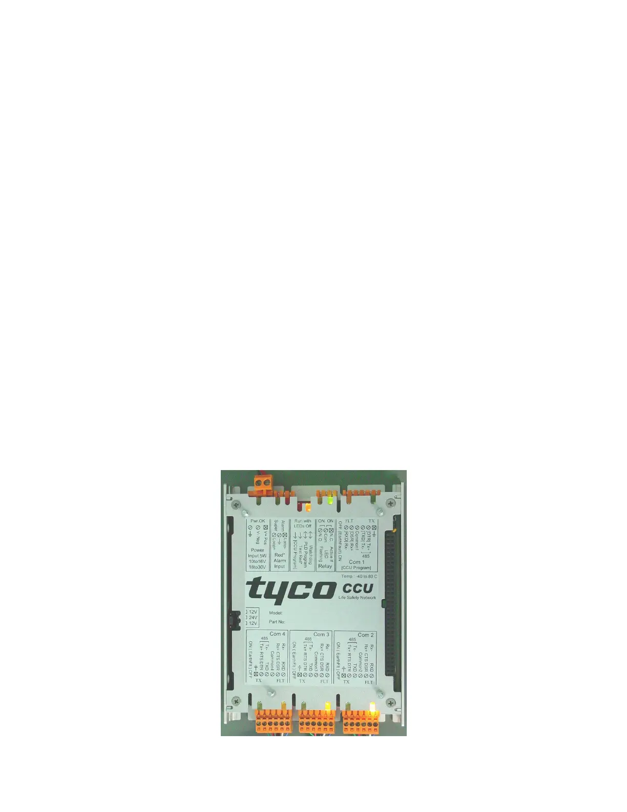 Loading...