F4000 LCD Operator's Manual Document No: LT0117
System Description
Page 2-2 19 April 2002 Issue 2.38
2.1 SYSTEM COMPONENTS
2.1.1 OVERVIEW
The F4000 is a fire detection system designed to cover a wide range of applications. It
performs the functions of the Control and Indicating Equipment (CIE), as specified by the
Australian Standards AS1603.4 for Automatic Fire Detection and Alarm Systems and
AS4050(INT) for Fire Fighters Control and Indication Facilities, and the New Zealand
Standard NZS4512 for Automatic Fire Alarm Systems in Buildings.
Figure 2.1 shows a block diagram of the F4000 System.
The F4000 Fire Alarm System consists of the following main components:
(a) A Fire Indicator Panel (FIP) containing an LCD Display and
(b) A number of "Responders" located around a Communications Loop. These
Responders, selected from a range of different types, provide the interface between
the various detection devices and the F4000 system.
(c) A number of optional Remote Zone Display Units (RZDUs) which mimic the FIP zone
displays at locations remote from the FIP.
2.1.2 F4000 FIRE INDICATOR PANEL (FIP)
The F4000 FIP is the heart of the F4000 system. It is microprocessor based and is the
MASTER display, operator control and Brigade Interface unit of the system.
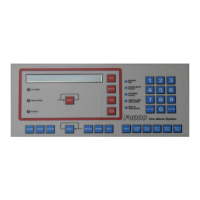
A front panel view of the F4000 LCD FIP is shown in Figure 2.2. This shows a standard
panel for up to 48 zones minimum. A 19" RAC cabinet version allows for 64 zones
minimum.
Specifically its functions are:
(a) To constantly communicate with all Responders via the communications loop, to
retrieve data from them, to transmit commands to them, and to monitor their integrity
at all times.
(b) To process the data obtained from the Responders and to generate displays and
annunciations as specified by AS1603.4, AS4050(INT), NZS4512 and any additional
requests as entered by the operator. This includes:
i) Up-dating the zone status LEDs to shown the ALARM, FAULT and
ISOLATED conditions.
ii) Controlling the relays that signal the Brigade.
 Loading...
