F4000 LCD Operator's Manual Document No: LT0117
System Description
Page 2-10 19 April 2002 Issue 2.38
2.2 LCD FIP DISPLAYS
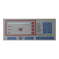
Figure 2.3 shows the front panel layout for an F4000 LCD FIP panel.
The F4000 FIP panel provides indications for:
(a) FFCIF Alarm, Fault and Isolate
(b) System Status
(c) Zone Status (optional)
There are 3 LEDs in the red-bordered FFCIF area that show common zone status:
(a) Alarm (b) Fault (c) Isolate
The SYSTEM STATUS INDICATORS are a column of 5 LEDs beside the numeric keypad,
that display the System Status information. The function of each LED is described alongside,
namely from top down:
(a) Mains ON (d) Ancillary Isolated
(b) CHGR/BATT Fault (e) Bells Isolated
(c) System Fault
In addition, New Zealand F4000 FIPs have an extra 3 SYSTEM STATUS indicators on the
display extender card:
(i) Normal (ii) Defect (iii) Fire
The optional ZONE STATUS INDICATORS display the status of each zone, whether an
Alarm Zone Circuit (AZC) or an Ancillary Control Zone (ACZ). Each zone has the following
three (3) indicators, and a space for installation dependent text, which is used to identify the
zone number and description.
(a) Red alarm "ALM" LED
(b) Amber fault "FLT" LED
(c) Amber isolated "ISO" LED.
An LED display card is fitted to show the zone status for each sixteen zones. The minimum
number of displays required at an F4000 LCD FIP panel is zero. However, 4 can be fitted in
the standard cabinet (FP0746) for displaying up to 64 zones. For New Zealand systems,
one of these positions will usually be taken up by the display extender board. Alternatively
the F4000 may be supplied in a rack cabinet configuration, which provides up to 64 zones in
each 7U module.
 Loading...
