26
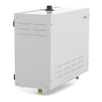
During operation the steam generator is emptied automatically after 4 hours (factory setting, via settings > auto emptying can be alte-
red) in order to ensure good water quality. When 2 or 3 generators are connected together, the ”Secondary”-generators are emptied at
20 minute intervals after the ”Primary” has been emptied.
The connections between the generators use a low power cable (4 core) with an RJ10 connector, (Fig. 16.)
Refer to the section ”Modular connector description” (Fig.17) for more information on the pin confi guration.
If one steam generator needs servicing the others can remain in operation. One generator that is set as a secondary is disconnected
by removing the cable from between the circuit boards. (Fig. 16)
If the generator that is to be serviced is set as the ”primary", do as follows:
1. Use the circuit breaker to switch off the generator.
2. Disconnect the cable that connects the control circuit boards (Fig. 16)
3. Select a ”secondary” steam generator and change the DIP switch settings to ”primary” according to the appropriate type. Refer to
Fig. 15. Then connect the control panel to the new ”primary”. A new ”initial setup” will be requested, as the generator had not been
set up as a ”primary” earlier.
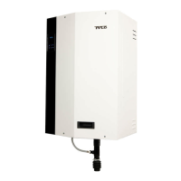
Modular connector description
Connecting components to the modular contacts (maximum cable cross-sectional area for RJ10. 0.9mm/ 0.2mm², AWG24)
Unit Pos Pin Comment
Temp.sensor (10kΩ) 1 2-3 Must be NTC type. May also be connected at Position 4.
External switch without LED indication 2 3-4 Both constant and impulse deactivation work.
External switch with LED indication 2 2-3-4 12VDC (maximum 40mA). Tylö external switch, item number: 9090 8045
Door contact without alarm for door status 3 3-4 Of type NO (Normally Open). Tylö door contact, Item No.: 9090 8035.
Door contact with alarm for door status 3 2-3-4 12VDC (max. 40mA)
1. NTC Sensor (RJ10)
2. External switch (RJ10)
3. Door contact (RJ10)
4. SEC/NTC Sensor (option) (RJ10)
5. Addon (option for Home)(RJ45)
6. RS485 control panels (RJ10)
7. RS485 control panels (RJ10)
8. RS485 control panels (RJ10)
9. RS485 control panels (RJ10)
10. Modular plug (RJ10)
11. Modular contact (RJ10)
Fig. 16
* = option
Fig. 17
1234Pin:
Pos 1.
NTC
Pin 1:
Pin 2: NTC
Pin 3: NTC
Pin 4:
Pos 2.
Ext sw
Pin 1:
Pin 2: LED
Pin 3: SW
Pin 4: 12 V
Pos 6-9.
4x RS485
Pin 1: A
Pin 2: B
Pin 3: 12 V
Pin 4: GND
Pos 3.
Door sw
Pin 1:
Pin 2: LED
Pin 3: SW
Pin 4: 12 V
Pos 4.
Bim/NTC
Pin 1: Bim
Pin 2: NTC
Pin 3: NTC
Pin 4: Bim
Pos 5.
Addon (option)
1234Pin:
10
11
12
6789
34 5
 Loading...