Vertical offset can be adjusted in three ways.
• When the channel is active, the signal is moved up and down the graphics area by holding and
dragging the touchscreen pen (left button if using the Mouse).
• When the Rotary-1 button is pressed once, the offset adjustment mode is entered. After switching
to offset mode, the offset level is changed by rotating Rotary-1.
• It is increased and decreased with the “Inc. Offset” and “Dec. Offset” buttons in the submenu of
the CH-1 menu. In addition, when the “Rst. Offset” button in the submenu is clicked, the offset
value is set to 0V.
Coupling adjustment:
The undesired signals can be filtered out by setting the coupling mode. For example, the signal under test is
a square waveform with DC offset.
• When the coupling mode is “DC”: the DC and AC components of the signal under test can both pass
the channel.
• When the coupling mode is “AC”: the DC components of the signal under test are blocked.
Click the “CH-1” menu button. The desired coupling can be selected with the “DC-Coupl.” and “AC-Coupl.”
buttons in the submenu.
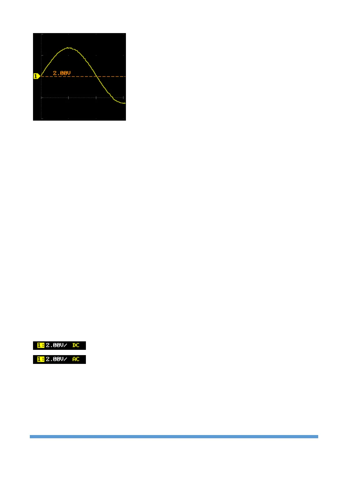
DC coupling
AC coupling