The parameter is set in three different ways.
• With the up-down arrows next to it,
• Entering numbers from the numeric keypad in the
parameter field and then clicking Enter,
• By scrolling the mouse cursor over the parameter.
While changing the parameter, the generated signal is updated instantly.
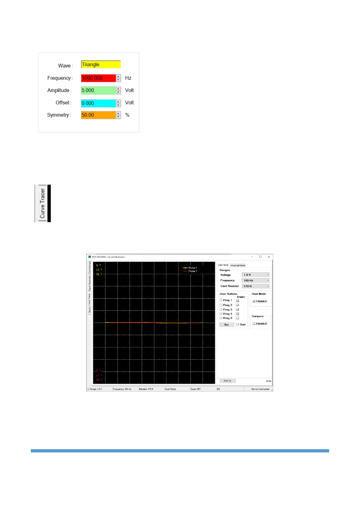
10.3. Curve tracer
Click on the “Curve Tracer” tab on the left to open the curve tracer menu.
The screen consists of two parts. On the left is the V-I impedance curve and on the right is the menu area.
The menu area consists of two tabs, “Basic Mode” and “Advanced Mode” (Figure 17).
Figure 17. Curve tracer overview
Basic Mode: It is the menu where basic settings such as test voltage, test frequency and source resistance
are made. In addition, scanning mode and dual channel operating mode settings are also made in this
menu (Figure 17).