If the Rotary-3 button is pressed in the stop mode, it is possible to view the sampled but not displayed data
by rotating the Rotary-3. At the top of the screen, it is shown which position of the buffer is reflected on
the screen.
3.6. Time base mode
The device supports two available time base modes: YT mode and XY mode. By default, the time-based
mode is YT.
YT mode:
In this mode, the Y-axis represents voltage and the X-axis represents time.
When the horizontal time base is greater than or equal to 25ms/div, the device enters slow scan mode.
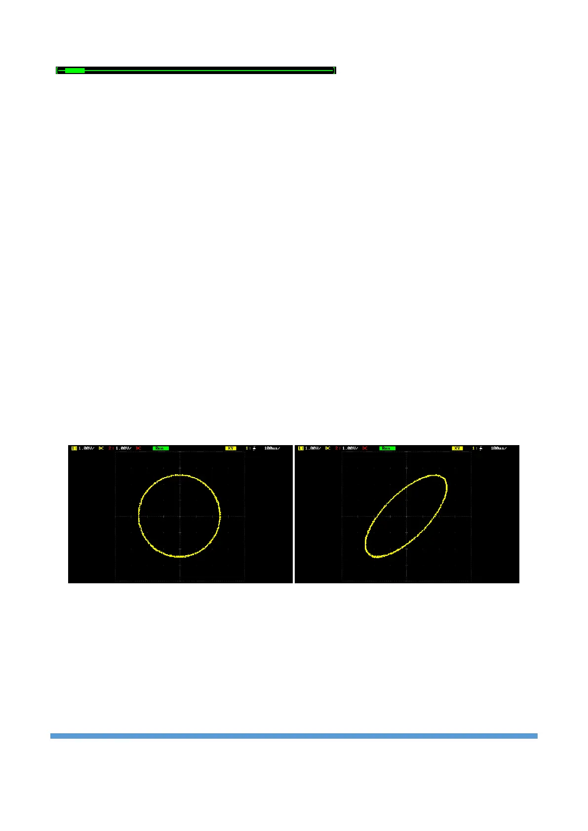
XY mode:
In this mode, both the X-axis and Y-axis represent voltage. The mode changes the screen from voltage-time
display mode to voltage-voltage display. You can use the Lissajous method to measure the phase deviation
of two input signals with the same frequency. Below, the same frequency and sinusoidal signals are applied
to both channels. The effect of the phase angle between the two signals on the signal is shown in the
picture below.
Phase angle 90° Phase angle 45°
Note: In XY mode, CH-1 and CH-2 are forced to be enabled.