3.1. Adjusting the vertical system
The UCE-DSO4200C has two analog input channels and each channel is equipped with an independent
vertical control system. The adjustment methods for the vertical systems of the two channels are the same.
This section takes CH-1 as an example to introduce the vertical system adjustment method.
Enable or disable analog channel:
Click the “CH-1” button in the menu to enable CH-1. While the “CH1-ON” button in the submenu enables
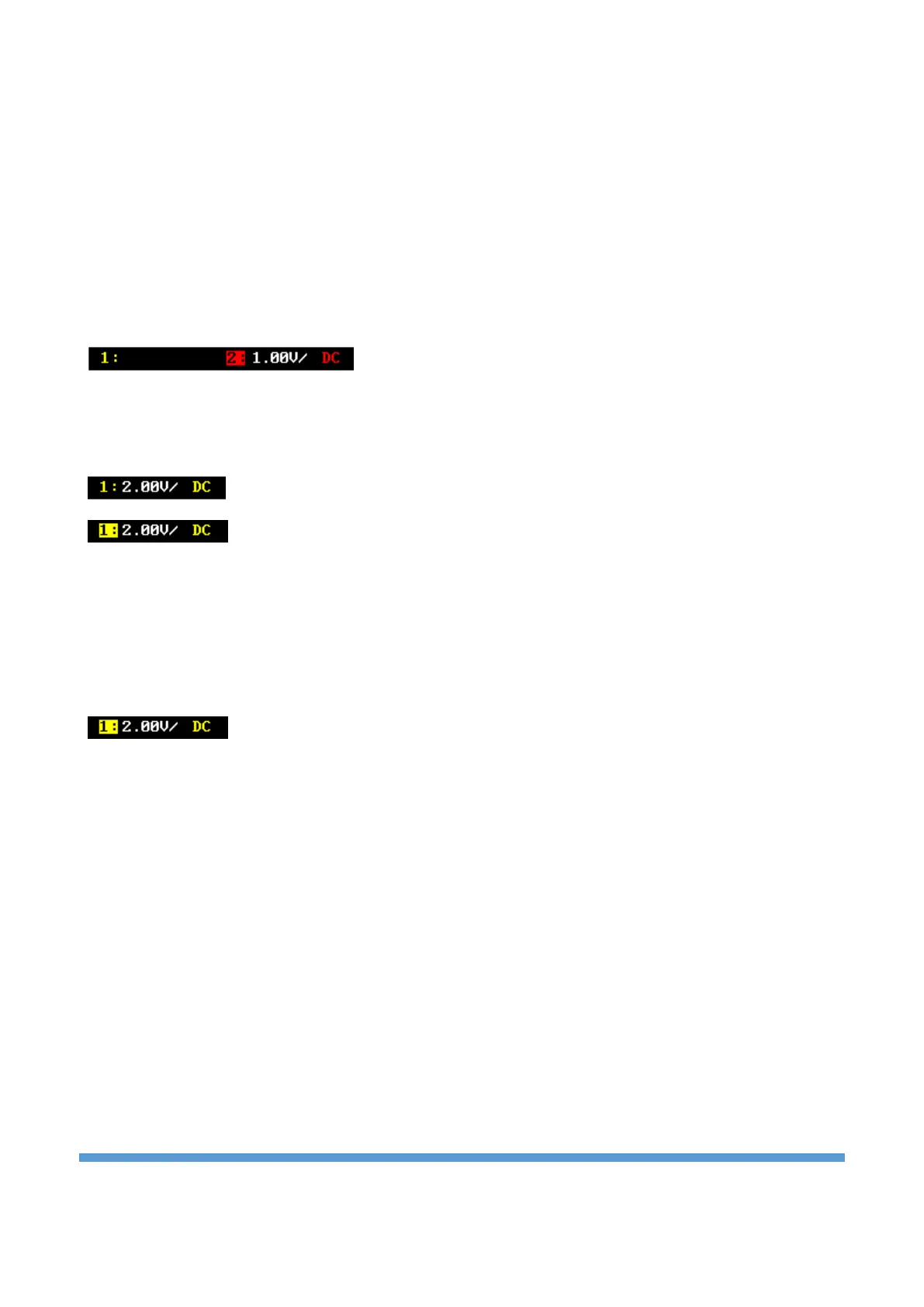
the channel, the “CH1-OFF” button makes the channel disable. In the figure below, CH-1 is disabled and CH-
2 channel is enable. No status information is displayed on the disabled channel.
If CH-1 is enabled but not activated, the channel status label is shown as below. Click the “CH-1” menu in
the menu to activate the channel. Other methods of channel activation are when the vertical scale setting
of the corresponding channel is made or if the rotary encoder button is clicked, the channel is activated.
CH-1 enabled but not active
CH-1 enabled and active
Vertical scale setting:
Vertical scale indicates the voltage value per grid in the vertical axis of the screen. It is often expressed in
V/div. While you adjust the vertical scale, the display amplitude of the waveform would enlarge or reduce.
The scale information of the channel status label (e.g., as shown in the following figure) at the top of the
screen would change accordingly.
The adjustable range of the vertical scale is between 5 mV/div and 10 V/div. Turn the Rotary-1
corresponding to CH-1 to adjust the vertical scale (clockwise to decrease the scale and counterclockwise to
increase). The vertically scaled channel becomes the active channel at the same time.
Vertical offset adjustment:
Vertical offset indicates the offset of the signal ground level position of the waveform from the screen
center in the vertical direction. When adjusting the vertical offset, the waveforms of the corresponding
channel moves up and down. As it moves, the offset level is shown on the screen with a horizontal line, and
the vertical offset information (as shown in the figure below) will change accordingly just above the offset
level line.