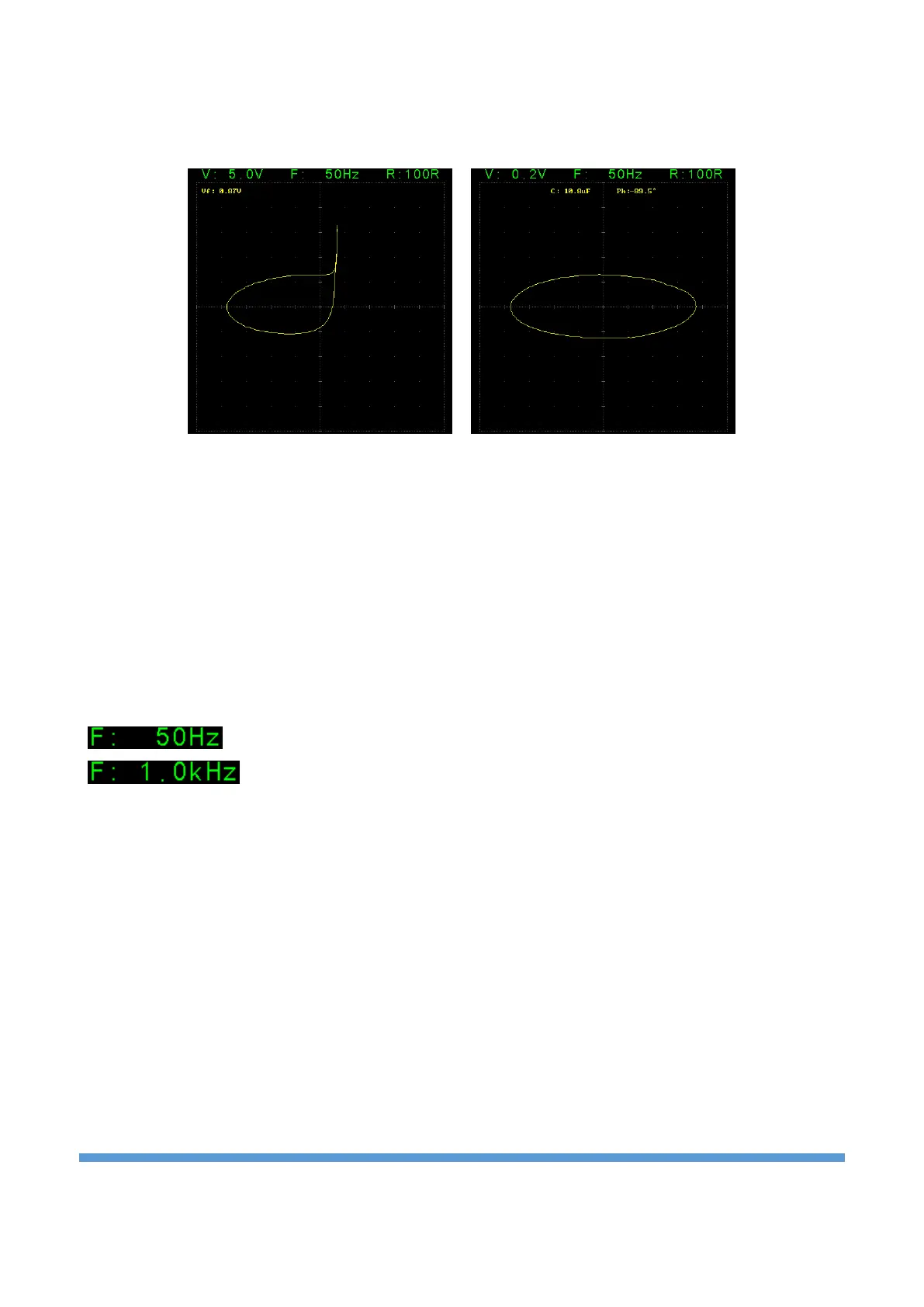
Figure 8 shows the impedance curves of a parallel connected diode and 10uF capacitor at 5V and 0.2V
stages. While a combination of diode and capacitor characteristics is seen at 5V, only the capacitor curve is
seen at 0.2V.
Figure 8. Impedance curve of parallel connected diode and capacitor at different stages
As seen in the examples above, the diode impedance is eliminated at the 0.2V stage and only the curves of
passive components such as resistors and capacitors are obtained. Thus, in the testing of electronic boards,
passive components can be tested independently of active components. There is a serious decrease in the
amount of components that need to be tested discretely by removing them from the electronic board.
Test frequency setting:
The test frequency can be adjusted between 20Hz and 10kHz. It is adjusted in 10Hz steps between 20Hz
and 200Hz, in 100Hz steps between 200Hz and 1kHz, and in 1kHz steps between 1kHz and 10kHz. It consists
of 36 levels in total. Rotate the Rotary-2 to adjust the frequency (counterclockwise to increase and
clockwise to decrease).
Passive components such as capacitors and coils are frequency sensitive. Frequency ranges are often
important in such component measurements.
• The low frequency - high current (e.g., 20Hz – 10R) range is suitable for high capacitance capacitors
(mF).
• High frequency – low current (e.g., 5kHz – 1K) stage is suitable for low capacitance capacitors (nF).
• The high frequency – high current (e.g., 10kHz – 10R) stage is suitable for coils with low inductance
(uH).
Limit resistance setting:
There are 7 different stages as 10R, 47R, 100R, 470R, 1K, 4.7K and 10K. Rotate the Rotary-3 to adjust the
limit resistor (counterclockwise to increase and clockwise to decrease).
10R is high current mode and 10K is low current mode.