24
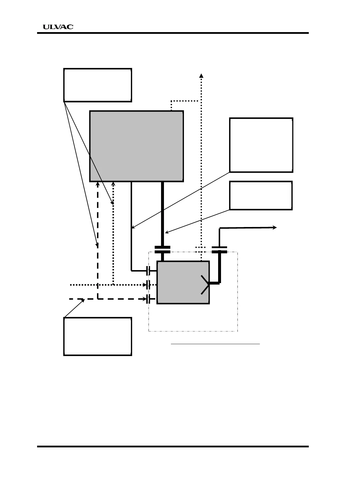
Location of vacuum pump in host device
Exhaust Duct
Signals for centralized
supervisory
HOST Device
Vacuum chamber
Vacuum
Pump
Electrical interface
Power Line
Control Line
Communication Line
Physical interface
Inlet Pipe,
Outlet pipe
Coverage of vacuum pump
Recipience utility from host
device
N2 gas
Cooling water etc.
Utility which does recipience
directly from plant facilities
N2 gas
Cooling water etc.
It is assumed that the pump stops suddenly when the interlock of the host device
does not synchronize with the interlock of the facility. It is necessary to manage
utility to give preventive measures. Do not use the utility not managed.


 To Next Page