UPO2000CS series User Manua
45
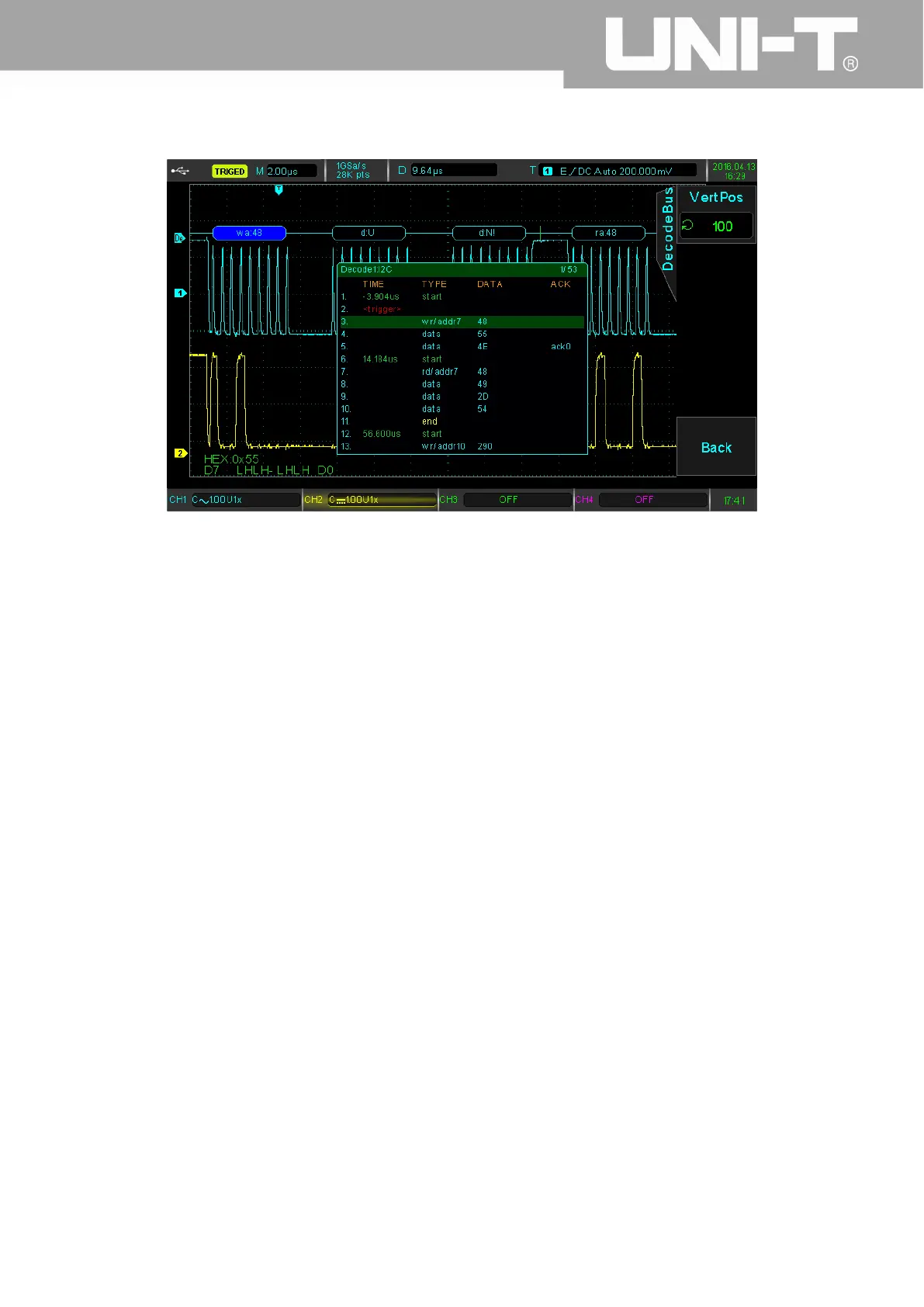
display is as follows:
As shown in the picture, the trigger position is event 3; the type is wr/addr7; the address is 0x48; the direction is
writing. The event 4 captured data is 0x55 (the corresponding letter is U), which gets response bit. The ACK series of the
event list do not indicate. Event 5 captured data is 0x4E. Because there is no response bit, the ACK series indicates ack0.
At the same time, the green “start” marks the time when I2C begin transmitting and the yellow “end” marks the time
when I2C stop transmitting. The present event list display 1/53 of the all events. The above event list function can
observe more decoding data.
SPI Protocol Trigger and Decode( Optional)
SPI interface is a kind of synchronized serial peripheral interface, which can make the host and all kinds of
peripheral equipment undertake communication through the serial methods. It is a kind of synchronous communication
bus of full duplex. It usually uses four signal lines: MOSI: the host data output, the slave data input; MISO: the host data
input, the slave output; SCLK: time signal the host transmits; CS: the slave chip selection enable signal.
SPI interface is mainly used to transmit the serial data between the host and low speed peripheral devices. The
data are transmitted according to the bit, that is to say, higher bit first and then lower bit. SPI interface do not need look
for the slave address. The communication is of full duplex and the protocol itself is easier. So it is widely used. SPI
protocol transmission is shown in the following picture.
 Loading...